This thread has been locked.

If you have a related question, please click the "Ask a related question" button in the top right corner. The newly created question will be automatically linked to this question.

SN75DP159: inter-pair and intra-pair skew

Part Number:

Dear David,

I have the same question as Sjoerd (intra- and interpair skew TMDS181) about the inter and intra-pair skew but now for the SN75DP159RGZ. We design a PCB with one HDMI input (for the connection to a camera) and one HDMI output (for a connection to a monitor). The HDMI output uses a SN75DP159 (output of the SN75DP159 is connected to the HDMI connector) and the HDMI input a TMDS181 (input of the TMDS181 is connected to the HDMI connector). The output of the SN75DP159 is connected by PCB traces to a HDMI connector.  The input of the TMDS181 is connected by PCB traces to  HDMI connector. For the PCB traces I have to know the inter- and intra pair skew.

The HDMI spec defines for the source at TP1 (at HDMI connector) the following skew values

Parameter TTP1 (HDMI2.0) TTP3(SN75DP159RGZ) Margin (left over for the PCB between TTP1 and TTP3)
Intrapair skew tolerance 0.15Tbit 0.15Tbit 0
Interpair skew tolerance 0.2Tcharacter 0.2Tcharacter 0

Remark: in the datasheet of the SN75DP159 is not defined  on which points the intra- and inter-pair skew iss measured but it is assumed that the values in the datasheet are measured on the TMDS data/clock pin of the chip (TTP3). Please confirm if this is correct.

If above is correct that I don't have any margin  for the PCB traces. Please can you give me the inter- and intra-pair skew for my PCB traces between the output of the SN75DP159 and HDMI connector?

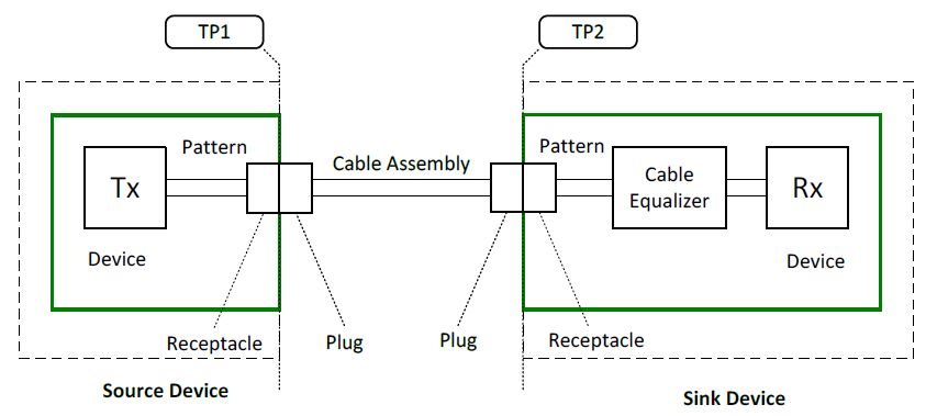
Figure 2: testpoints according HDMI spec

I have the same question as described above but now for the inter- and intra-pair skew of the PCB traces between the HDMI connector and the input of the TMDS181.

Parameter TTP2 (HDMI2.0) TTP2 (TMDS181) Margin (left over for the PCB between TTP2 and TTP2)
Intrapair skew tolerance 0.15Tbit+112ps 0.15Tbit+112ps (for 3.4G < Rbit < 6.0G) 0
Interpair skew tolerance 0.2Tcharacter+1.78ns 0.2Tcharacter+1.78ns 0

Thanks and in advance,

Marcel

  • Marcel

    Why do you need to design with both TMDS181 and DP159? I am concerned that you might over-equalize the signal with cascading the TMDS181 and DP159 on the same signal path. 

    For the inter-pair and the intra-pair skew, please follow the HDMI 2.0 spec on the inter-pair and intra-pair skew requirement. Please also refer to this TI HDMI design guideline. 5684.Texas Instruments HDMI Design Guide.pdf

    I would also recommend placing common mode choke on the HDMI output connector that will help passing the intra-pair skew compliance testing.

    Thanks

    David

  • David,

    Maybe I was not clear but the TMDS181 and SN75DP159 are not cascaded in the same signal path. I have a product with 2 HDMI connectors; one HDMI IN connector and one HDMI OUT connector. The HDMI connector IN is applied to an external camera and the HDMI OUT connector to a monitor. For each path a different TMDS translator is used (output TMDS181 connected to the HDMI output connector and the input of the SN75DP159 to the HDMI input connector).

    Thanks for the TI HDMI design guideline and I understand what's described there but the problem is that there seems be something wrong in the TMDS and SN datasheets because the max allowed intra- (112ps) and inter-pair (1.8ns) skews on the input of the chip in the TI datasheet (related to point TTP2; see picture below) is less than the max allowed intra- (0.15Tbit+112ps) and interpair skew (0.2Tchar+1.78ns) on TTP1 (is the same point as TP2 of figure 2 as shown in my previous mail) as described in the HDMI2.0 spec. This means that I have a negative skew margin for the PCB traces and this cannot be true. This point is also discussed by Sjoerd.

    For the output intra- (0.15Tbit) and inter-pair (0.2Tchar) skews of the TMDS and SN chips I miss the testpoints where these values are measured (but I expect that this is related to TTP3). Please confirm.

    When I compare the output intra- and inter-pair skew of the TMDS and SN datasheets with the HDMI2.0 spec (according the HDMI spec the max allowed intra- (0.15Tbit) and inter-pair (0.2Tchar) skews at TTP4 (is the same point as TP1 of figure 2 as shown in my previous mail) ) then I conclude that I have 0 skew margin for the intra-and interpair skew for the PCB traces and this can also be not true.

    Please can you provide me the following information:

    1) the max intra- and inter pair skew for the PCB traces connected to the input of the SN75DP159?

    2) the max intra- and inter pair skew for the PCB traces connected to the output of the SN75DP159?

    3) the max intra- and inter pair skew for the PCB traces connected to the input of the TMDS181?

    4) the max intra- and inter pair skew for the PCB traces connected to the output of the TMDS181?

    Regards,

    Marcel

    Figure 3: Testpoints TMDS and SN

  • Marcel

    For both DP159 and TMDS181, the input inter-pair skew in the datasheet should read:  T_RX_INTER: 0.2*Tcharacter +1.78 ns  This matches the HDMI  specification and is where the number originates.

    For the input intra-pair skew, it should read: T_RX_INTRA:  0.15Tbit + 112ps, follow the HDMI spec as well.

    The output inter-pair and intra-pair skew are correct in the datasheet.

    Thanks

    David

  • Hi David,

    The HDMI spec defines the inter- and intra-pair skew to the interface connectors of a black box. Inside the black box there is a signal path from connector to the TMDS/SN chip. So do you agree that when the intra- and inter-pair skews of the TMDS/SN chip are the same as the HDMI spec that I don't have any skew margin for the signal path (PCB traces)?
    Regards,
    Marcel
  • Marcel

    If only specifying the skew at the connector, then there is a potential that the max skew at the connector plus the skew from the board routing may exceed the de-skew capability of DP159/TMDS181 when in re-timer mode, so we have to specify the skew requirement at the pin level.  

    In a typical application, the distance between the TMDS device and the connector is quite short. Even for example, with a 5mil inter-pair skew, that is only ~0.85ps assuming propagation delay is 170ps/in. It is a negligible part of the overall skew budget consider the total skew budget is T_RX_INTER: 0.2*Tcharacter +1.78 ns.

    Thanks

    David