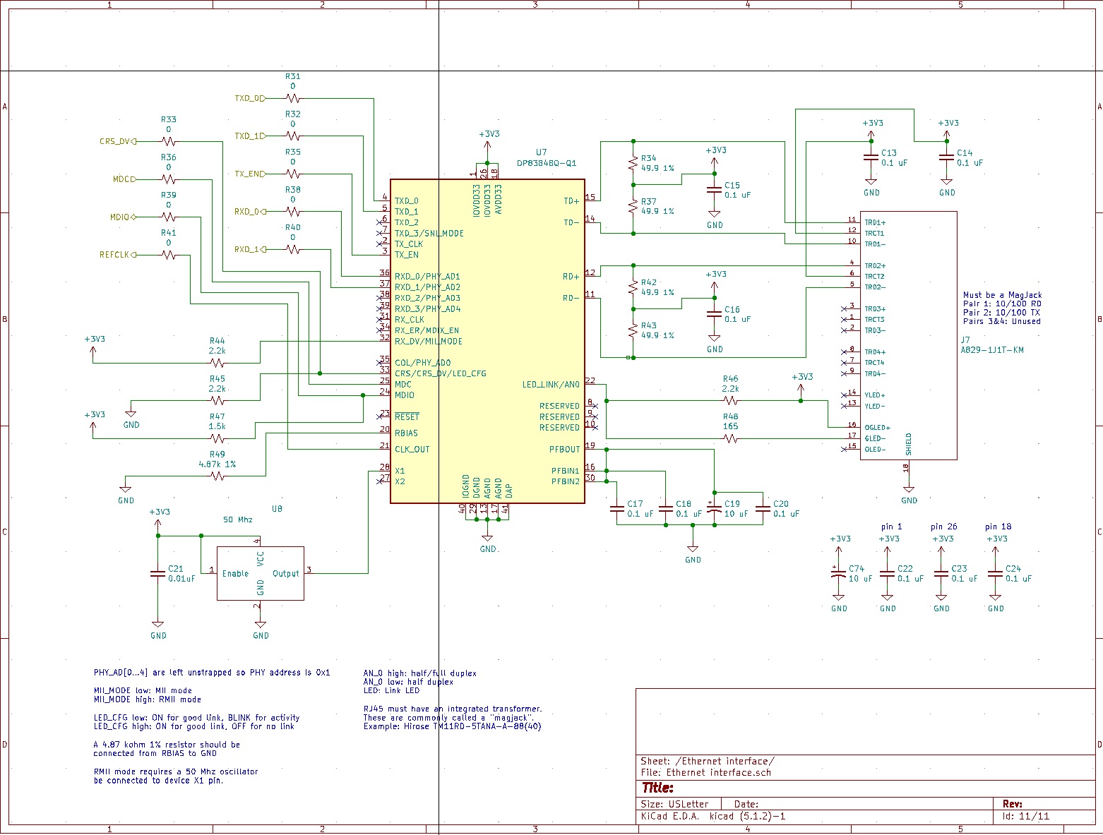
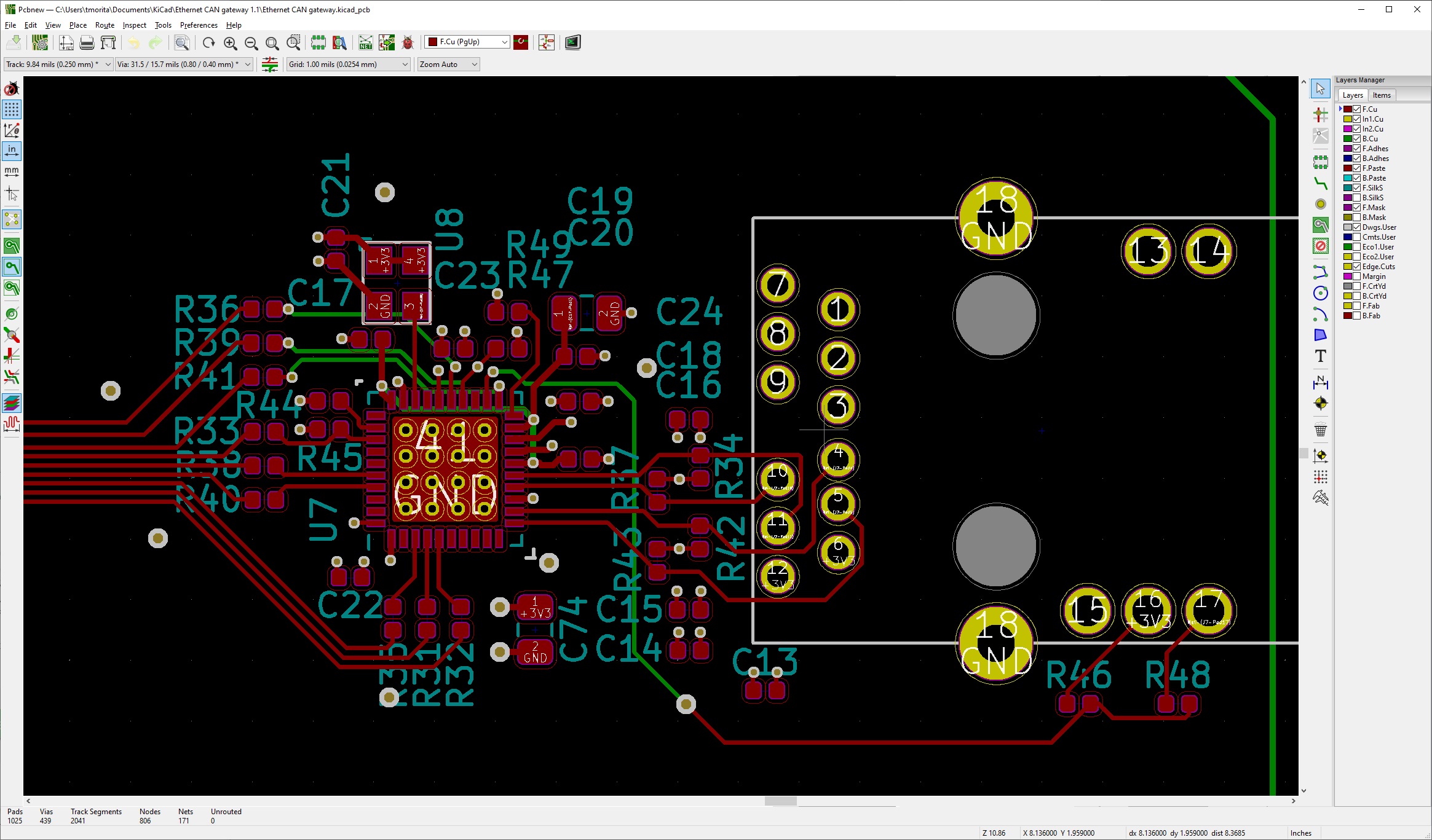
I just realized on the board where I have a non-working DP83848Q-Q1, I forgot to ground the DAP.
1. is the DAP required to be grounded for proper operation?
2. What are the symptoms of the DAP not being grounded?
Original question:

I just realized on the board where I have a non-working DP83848Q-Q1, I forgot to ground the DAP.
1. is the DAP required to be grounded for proper operation?
2. What are the symptoms of the DAP not being grounded?