Dear Sir,
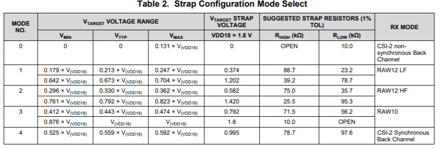
My customer would use DS90UB933/ DS90UB954 RAW10 setting.
Please you kindly review below setting & give us advise.
for DS90UB933:
- Adjust Mode resister value by internal or external PCLK
- 0x05[2:0]=1
- 0x14[2:1]=01
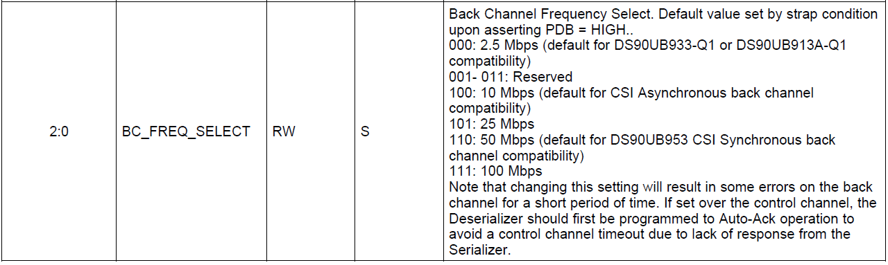
for DS90UB954
- Adjust Mode resister value by RAW10
- 0x70[7:6] & [5:0]
- 0x6D[1:0]=11
- 0x7C[7:6]=00
Thanks!
Steven