This thread has been locked.

If you have a related question, please click the "Ask a related question" button in the top right corner. The newly created question will be automatically linked to this question.

DP83867E: DP83867E not establish link when plugged into a computer

Part Number: DP83867E

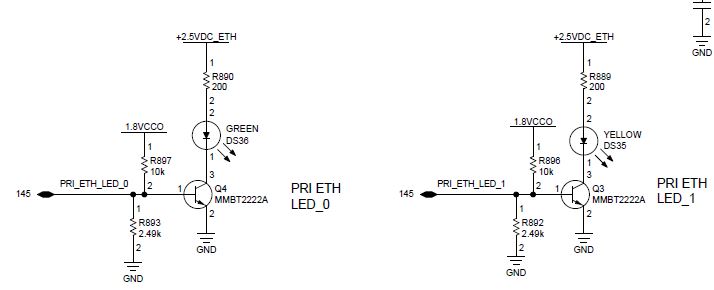
I am using a DP83867ERGZ in my design along with an RJ45 with integrated magnetics.  I have a 10k pull-up on the Reset pin.  

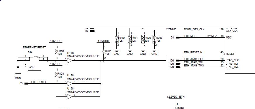
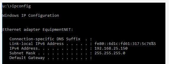
When I initially power up no link is established between the  DP83867ERGZ and the computer.  When I press S14 for longer than 1us, the PC still does not recognize the DP83867ERGZ.  Note RESET is either 6mV (when S14 is pressed) or +1.8VDC.  There is no pull-up on ETH_RESET (it comes from a unprogrammed FPGA currently).  The only way I can get the PC to establish link with the  DP83867ERGZ is by touching pin 43 with the positive lead from a HP34401A (neg lead connected to GND).  Removal of U128 did not make any difference.  When working I get the following:

Any ideas as to what might be causing the lack of linkl?  I noticed this issue on the two PWBs I've checked.

Also is there any way I can test the DP83867ERGZ once the link is established eventhough the RGMII signals are going directly to the unprogrammed FPGA?


  • HI,

    It's essentially points to that PHY is not getting out of reset at Power UP.

    Have you verified that the board matches the power up timing specified in datasheet ?

    What's the VDDIO you are using on the board ?

    For data transfer, few options :

    a. DP83867 has inbuilt Packet Generator which can be used for testing the packets. However these are preconfigured random packets and can't control the contents.

    b. Configure DP83867 in reverse loop back mode, it will loop back the data it received on the MDI.

    Regards,

    Geet

  • VDDIO = +1.8V.   The +2.5V power supply provides power to the DP83867 only.  So I'm assuming the note under Table 107 (pg 97) of the datasheet would apply.  It states "If the 2.5-V power supply provides power to DP83867 devices only, the 1.8-V supply may ramp up at any time before 2.5-V".  So on my PWB design +1.8V is up before the +2.5V supply.  By the way removal of U128 and R894 did not have any impact.  Still need to touch pin 43 of the DP83867 with a multi-meter to get it to establish link.     

  • Why would pressing the reset push button again after power rails are stable (regardless of power up sequence) not reset the DP83867 and allow it to link to the PC?

  • When we probe INT_PWDN with a volt meter we found that link is lost (LEDs go off).  If the DMM probe is held on pin 44 for a consistant longer period of time the LEDs will eventually turn back on.  Probing with a scope does not result in any of these phenomenons.  Why would this part be so sensitive to probing with a DMM?  Again the PHY has its own +2.5V supply so do I still need to sequence the VDDA1P8?   We are seeing the same issues on the 5 PWBs.         

  • INT_PWDN pin is by default configured for Input PowerDown. May be probing is pulling the pin down and causing PHY to enter IEEE Power Down mode.

    Regards,

    Geet

  • So pin 38 (RX_CTRL) went directly to a FPGA I/O.  I added a 2.49k pull-up resistor to this signal which would select Mode 4 and enable Auto-Negotiation.  LED_0 and LED_1 circuit was as follows:

    I went ahead and had both R897 and R893 removed along with R892 and R896.   I think this sets LED_0 to Mode 1, Mirror Enable = disabled and SGMII Enable = disabled.  I don't fully understand the mirror enable but the DP83867 in my application is being used in RGMII.  This change then set LED_1 to Mode 1, ANEG_SEL = 0 for 10/100/1000.  All these changes were made and the DP83867 linked with the computer when the ethernet cable was plugged into the RJ45 connector on my board.  All LEDs came on and LED 0 flashed periodically. 

    I wish there was more specific information or specific examples on how, why, and to what to set the straps.  I did find http://www.ti.com/lit/an/snla258a/snla258a.pdf which was helpful but it mainly describes setting the addressing and doesn't explain when specific modes related to LED_0 and LED_1 are needed.    


  • Clarification - it turns out the 2.49k pull-up that was added on pin 38 (RX_CTRL) actually went to GND (so actually a pull-down).  When we changed it to be pull-up, initial linking with the computer did not work.  We ended up changing pin 38 (RX_CTRL) configuration to Mode 3, and everything worked again.