This thread has been locked.

If you have a related question, please click the "Ask a related question" button in the top right corner. The newly created question will be automatically linked to this question.

SN65HVD251: CAN bus termination

Part Number: SN65HVD251

Hi Experts,

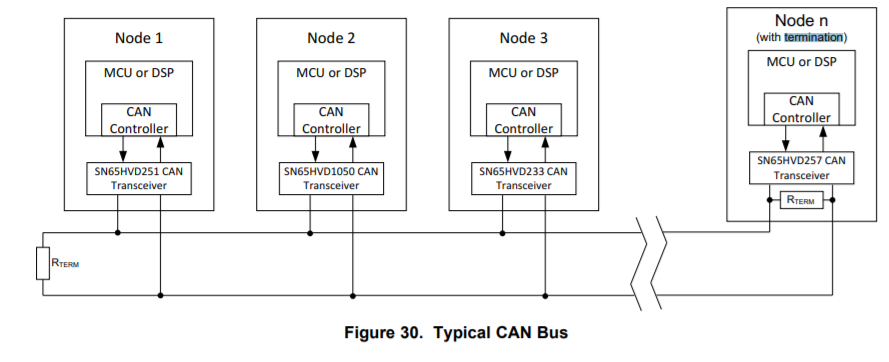
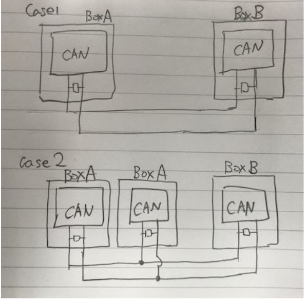
In my understanding, the termination register for CAN bus should be placed at the each edges of CAN network. So if each nodes have the termination register inside the box as below, it should be problem. Is this understanding correct?

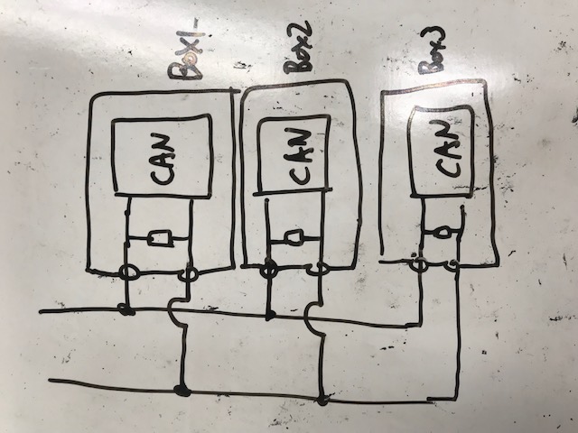
If this usage model is the problem, do you have any solution?

Regards,

Hisao Uchikoshi

  • Hi Hisao-san,

    CAN termination should be done at either end of the network. This means to say at the first node and last node only. This can be done within the node itself or externally as shown in the diagram. ISO11898-2 specifies the driver differential output with a 60-Ω load (two 120-Ω termination resistors in parallel). More than 60-Ohm loading on the bus (adding termination on every node) would make it increasingly difficult for the transceivers to drive a dominant on the bus.  

    The diagram you show with termination on every node will likely overload the bus and make it impossible for the transceivers to pull the lines far enough apart for proper communication. I would recommend removing (not populating) these resistors in all nodes except the two ends of the network. 

    Let me know if you would like further clarification or recommendations.

    Regards,

    Eric

  • Hi Hisao-san,

    A comment on my previous reply:

    I assumed the termination values of 120-Ohms on each node. If larger values are used for stub termination (1k - 2k-Ohm), a network such as the one you drew is possible without overloading the bus. 

    Regards,

    Eric

  • Hi Eric,

    Thank you for your reply. Please see below figure.

    There are two equipment, A and B. Usually, A and B is the either end of the network. This is the case 1.

    Sometimes, two A are required. Even for this case, we want to use the two exact same A. This is the case 2. 

    Our question is how to realize it. Do you have any solution for the case 2?

    Regards,

    Hisao Uchikoshi

  • Hi Hisao-san,

    If all termination values are 120-Ohm, I would recommend removing the termination resistor on the second (stub) A unit in case 2. If three 120-Ohm loads are present on the bus, the device drivers may not be able to drive the equivalent 40-Ohm load. 

    If all A units must be identical, the termination resistors could be left un-populated or a larger value (1k-2k-Ohm) could be used and 120-Ohm termination could be applied directly to the end of the bus.

    I hope this helps. Let me know if you would like other recommendations.

    Regards,

    Eric