This thread has been locked.

If you have a related question, please click the "Ask a related question" button in the top right corner. The newly created question will be automatically linked to this question.

TPD6E05U06: How to connect the GND pins?

Genius 3870 points
Part Number: TPD6E05U06

Hi 

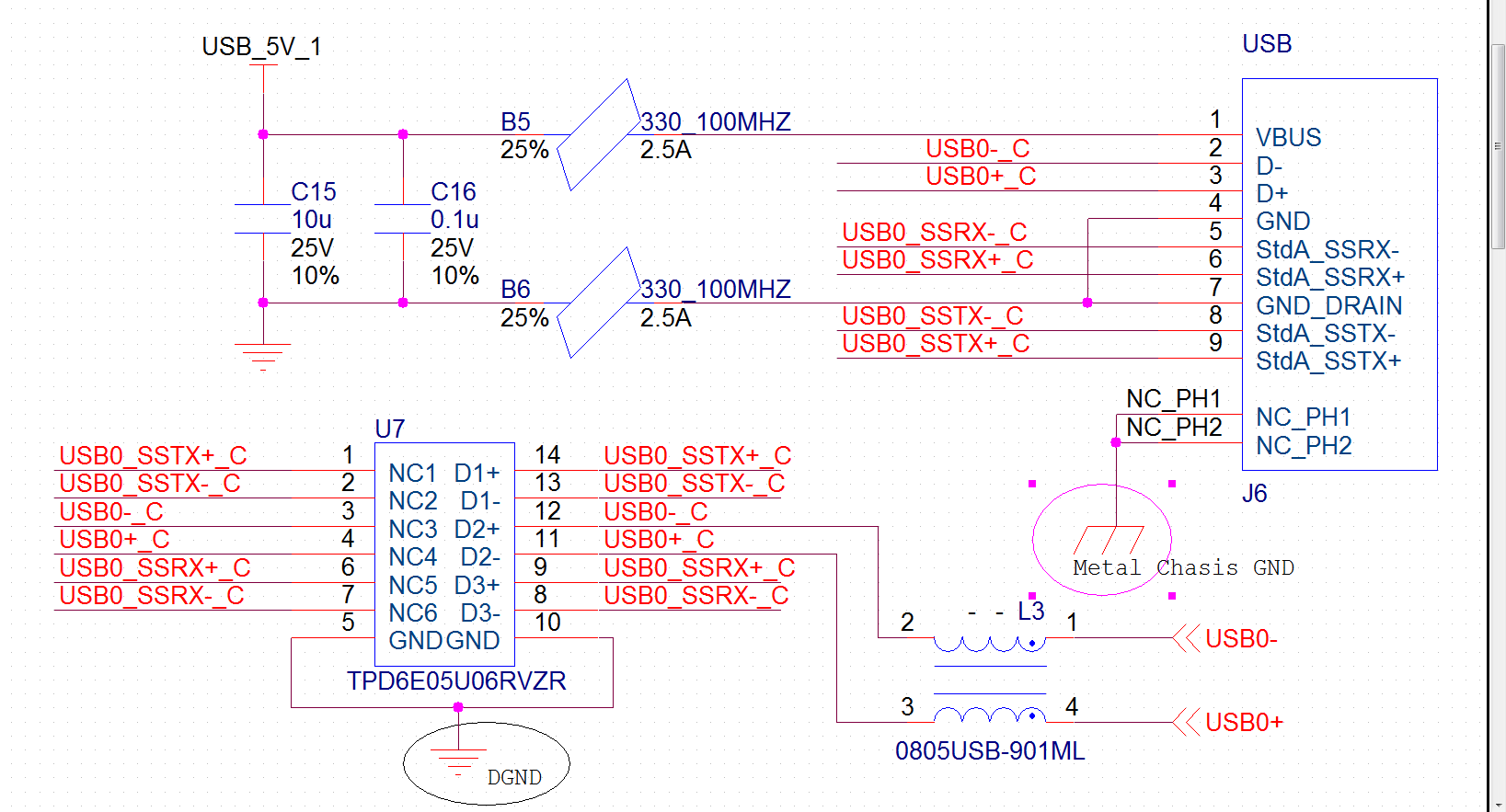
we are using TPD6E05U06RVZR to protect USB 3.0 interfaces on a device, with metal  enclosure(chasis) and internal IO PCB board.

SCH as below. Should I connect GND pins of TPD6E05U06RVZR to DGND(digital signal GND) or Metal Chasis GND (the metal enclosure) to ensure pass a 8-kv contact ESD test ?

Pls note the NC_PH1/2 pins are the  two fix pins of usb connector.

Thanks. Any suggetions are welcome.

  • Hello,

    Where are you connecting DGND to metal Chasis GND? If they are not shorted together then I would keep it as is. If they are shorted together then you can move it to metal chasis but you do not have to.

  • Hi Cameron 

    Your question is also one of my concerns. Not sure whether need to short DGND with Chasis GND, so I reserved some 0 ohm resistors between two grounds on PCB. Do I need to connect them together, on single-point or multiple points ?

    I read on Henry Ott book of EMC that transient suppressor device should be grounded to metal chasis, that seems reasonable, because ESD current should be conducted to flow along chasis and not go into PCB board that inside chasis. 

    As a new guy on EMC design, I appreciate if you could further explain on your opinion. Thanks very much. 

  • Hello,

    For best "transient suppression" you definitely want to have the path for the ESD event to go from point of contact to GND be as small as possible to prevent coupling. Also if you have it ground to the metal Chasis  then you are minimizing the GND disturbances on your signal plane which is good as well.

    However, ESD devices have a working voltage and a breakdown voltage that is with reference to the GND that you put them on. If you ground the ESD device to the chasis and put it on the signal line without having the chasis shorted to your signal ground, you cannot know at what potential the chasis is at vs your signal ground so there is potential that you will turn on the ESD diode when it is not meant to be turned on.

    The best solution would be to have your chasis grounded to your signal ground through 0Ohm resistor like you have that keeps the two at the same potential but minimizes the impact of any ground bounces on your signal ground if something happens on the chasis and ground your esd device to the chasis as well since it will be the same as your signal ground you know it will not have a false trigger since you chose the device based on your signals working voltage.