


Part Number: SN65DP159
Hello.
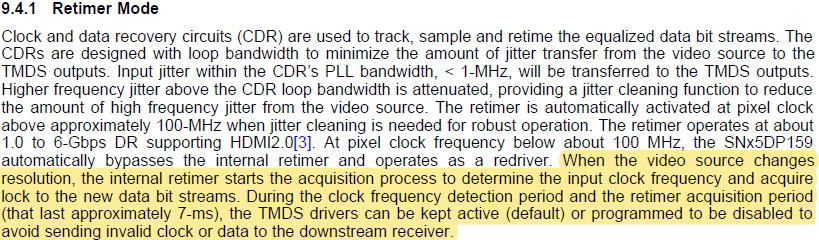
Please tell us how to stop the output during the retimer mode clock detection and retimer setting period.
There is a sentence in 9.4.1 of the data sheet that output can be stopped.
Best Regards,
Part Number: SN65DP159
Hello.
Please tell us how to stop the output during the retimer mode clock detection and retimer setting period.
There is a sentence in 9.4.1 of the data sheet that output can be stopped.
Best Regards,
