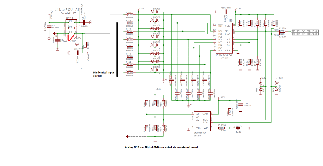
We use a PCA9545 I2C Port Extender Chip.
In our application, we use the 8 Digital I/O-lines as inputs (also programmed by software).
Sometimes, we don't know when and why, one or more input's will be damaged or don't work correctly.
When this happens, it's not possible to read the status of these input pins, normally we see a high, when this input was damaged.
We are searching for the root cause of this failure, but we can’t solve it up to now.
We have this inaccurate circuit design at the digital inputs:
In front of all of these digital inputs we use at each pin a RC-low-pass-filter.
The designer of these board placed 1.1kOhm to +5V (when it goes to High) and 100 Ohm (when it goes to LOW) and 100nF to ground.
The rise and fall times of the Port-Pin’s at IO0 .. IO7 are very high, much too high, I guess ..
- Rise time at a Port-pin IOx:: Tau = R * C --> 1.1kOhm * 100nF = 110uS
- Fall time at a Port-pin IOx: Tau = R * C --> 100Ohm * 100nF = 10uS
It’s more unknown instead of a common knowledge in the electronics family, I guess, rise and fall times of CMOS input circuits mustn’t be higher than 100ns …1us max, otherwise a Schmitt-Trigger input should be used. Unfortunately, this max. rise and fall times of the Digital I/O-Pin’s can’t be found in a datasheet ….
My question to the application engineers of TI and to the community:
Do you see a plausibility to destroy an input circuit by driving these inputs with this high rise times which are longer than 50 us in our application?
May calculation of the rise time at the dangerous area between TTL low and TTL high:
Tau = 110us --> from max. TTL-low level of 0.8V to the min TTL-high level of 2.0V --> I would say, half of Tau is a correct value during the transition --> so I think it’s more than 50us


