This thread has been locked.

If you have a related question, please click the "Ask a related question" button in the top right corner. The newly created question will be automatically linked to this question.

DS90UB948-Q1: The color bar of pattern generation is overall offseting to the right

Part Number: DS90UB948-Q1

Dear team,

My customer use the pattern generation with internal clock in the 948, but the the overall picture offset to the right, could you please tell me the reason?

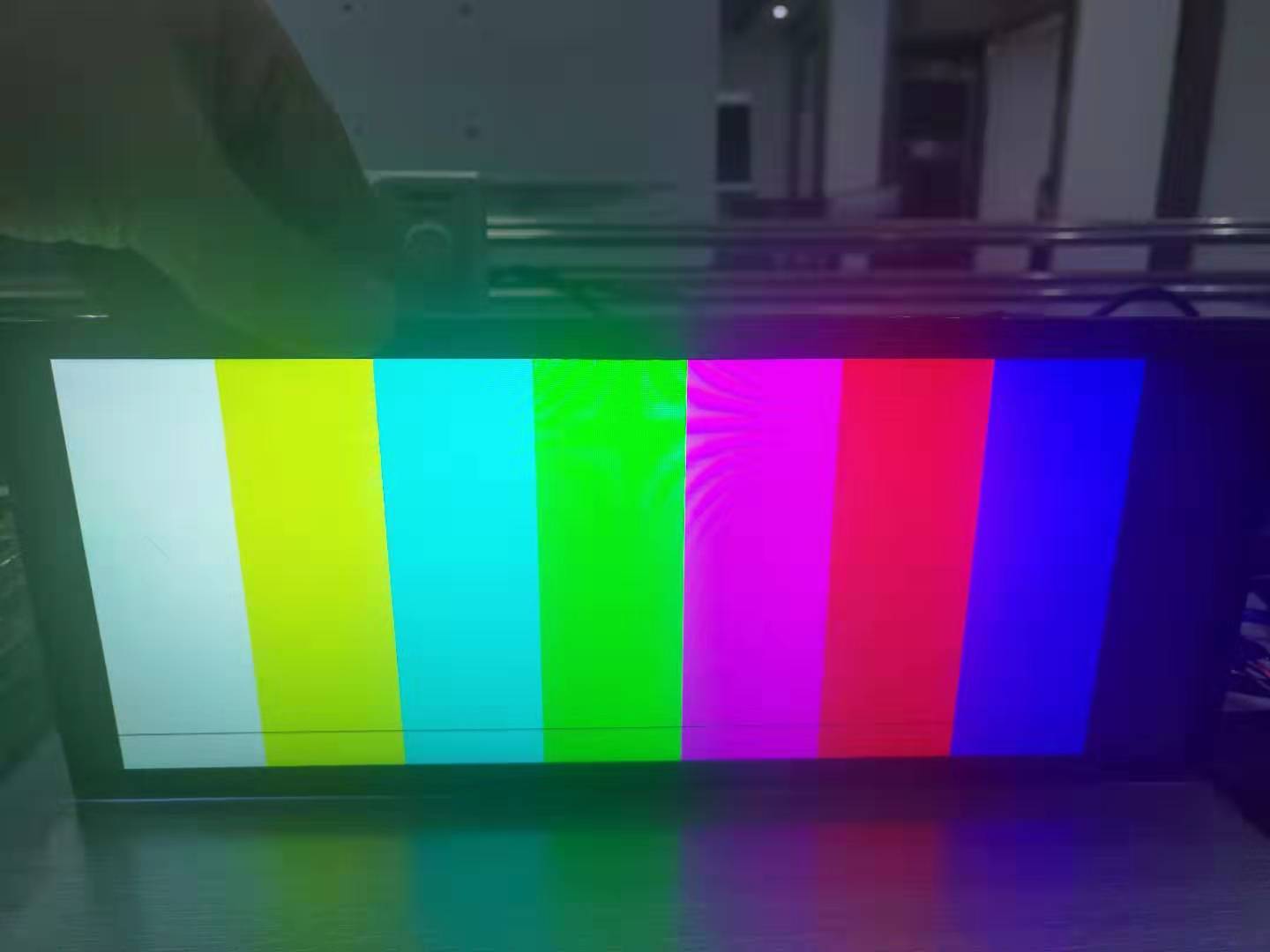
The picture is as below, as we can see at the left there is a black border while this part should be white.

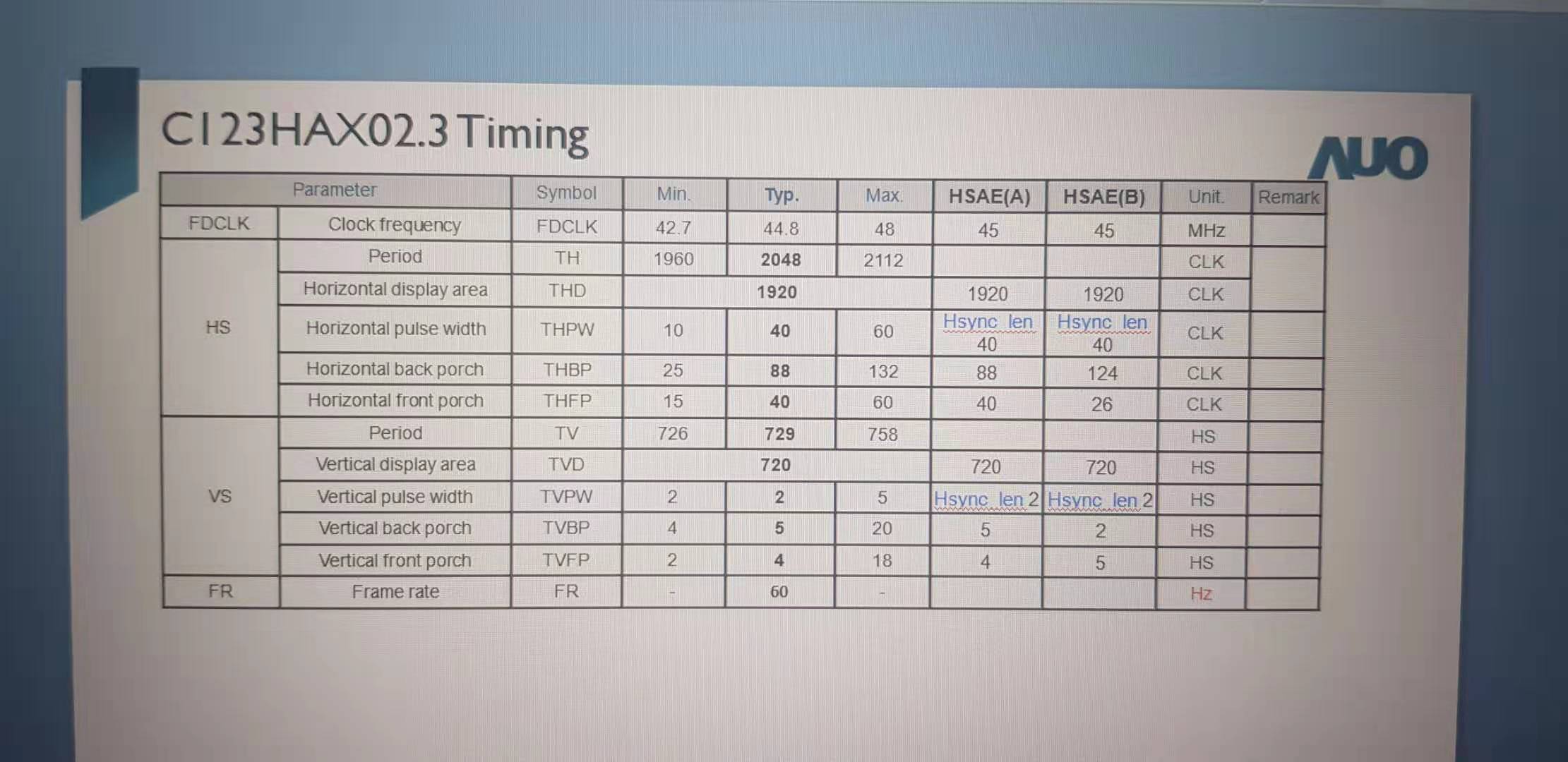
The screen specification is as below,

The pattern generation is as below,(below is the typical value, I also tried the max value in above specification picture, but the result is the same)

0x66 = 0x03
0x67 = 0x04

0x66 = 0x04
0x67 = 0x00

0x66 = 0x05
0x67 = 0x28

0x66 = 0x06
0x67 = 0xD9

0x66 = 0x07
0x67 = 0x80

0x66 = 0x08
0x67 = 0x07

0x66 = 0x09
0x67 = 0x2D

0x66 = 0x0A
0x67 = 0x28

0x66 = 0x0B
0x67 = 0x02

0x66 = 0x0C
0x67 = 0x58

0x66 = 0x0D
0x67 = 0x05

0x65 = 0x06
0x64 = 0x05

Thanks & Best Regards,

Sherry

  • Hello Sherry,

    This looks like a dual OLDI panel so please first make sure that the 948 is configured for dual OLDI output. Next, based on the screen dimensions and frame rate it should be noted that the PCLK shown in the table is for each OLDI output, so the total PCLK should be 44.8*2 = 89.6MHz. 

    Also note that for 948, the internal oscillator is ~140MHz (see this app note table 2): http://www.ti.com/lit/an/snla132d/snla132d.pdf

    So you will not be able to generate exactly this PCLK value. The closest would be ~70MHz (140/2). 

    Also your configured vertical total dimension is incorrect. Right now it is 0xD92 = 3474 lines. It should be 0x2D9 = 729

    For register 0x65 you are setting bit 1 for color bar inversion - why is that? Maybe you have MAPSEL set incorrectly for the panel? 

    Please try fixing these commands:

    0x66 = 0x03
    0x67 = 0x02

    0x66 = 0x05
    0x67 = 0x98

    0x66 = 0x06
    0x67 = 0x2D

    Note that this will still give a nominal PCLK for ~70MHz so it may not display correctly depending on the panel tolerance. If you need to generate a more specific PCLK frequency then you may need to connect a serializer device to supply an external PCLK at the desired rate. 

    Best Regards,

    Casey