This thread has been locked.

If you have a related question, please click the "Ask a related question" button in the top right corner. The newly created question will be automatically linked to this question.

DS90UB934-Q1: DS90UB953

Part Number: DS90UB934-Q1
Other Parts Discussed in Thread: DS90UB953-Q1

Hi Team,

We have a problem about how to use TI SERDES in application.

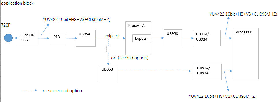
in our system,there are two processors, one named A with MIPI-CSI2 TX  and MIPI-CSI2 RX interface, the other processor named B is parallel interface input.

A camera is connected to processor A via mipi csi2 RX interface ,camera image format is YUV422 10bit+HS+VS clk=96mhz
processor A can also bypass output the camera image via mipi csi2 TX interface

processor B want to receive the bypass output image from mipi csi2 TX interface of processor A

processor A bypass output with DS90UB953 as serializer, processor B with DS90UB934 as deserializer
from snla270a.pdf ,we know we need to calculate date rate ,

in snla270a.PDF, table15(setup example using external clkin mode)
but I do not know the meaning of RX PCLK from table15,I know there is a PCLK Singal in UB934,
can you tell me what is the difference between PCLK and RX PCLK

in UB913 Datasheet,there are two sentences,
one is 10-bit payload up to 100mhz,the other is 12-bit payload up to 75mhz,
100mhz/75mhz means RX PCLK or means PCLK?

there is a note in snla270a.pdf as below
It is important that the sensor be synced to the external clock (either
directly or by the DS90UB953-Q1 CLKOUT), because a variation or drift in CSI-2 data could cause buffer overflows.

but in our system, DS90UB953-Q1 CLKOUT cannot be connected to processor A
how to use the DS90UB953-Q1 CLKOUT
Are there any problems if we donot use DS90UB953-Q1 CLKOUT?

  • Hi,

    Take a look at section 6 (Data Rate Calculations), this shows how RXPCLK is derived from CLKIN (). PCLK in reference to the 913 datasheet is discussing the clock coming in from the Imager as a reference for the PLL.

    Regards,
    Mandeep Singh

  • Hi,

    I'll explain the approach to setting up 953 with 934.

    1) The first step is to know what is the total Parallel output that is going to be sent out from the 934 and into Processor B. Let's take an example and say that it's 450Mbps.

    2) The next step is to determine what is the mode that the 934 will be set-up in, let's take an example and say it's RAW 12 HF.

    3) The next step is to know what is the RX PCLK or the PCLK output. This is the PCLK that the 934 transmits with the output data. Why we need to know this? It's because in this DVP mode, the CSI-2 throughput must match the Parallel output of the 934, any difference will cause issues. We keep specific ratios because knowing and understanding these helps match the CSI-2 throughput with Parallel output.

    a) Now, the RX PCLK is going to equal (RXPCLK = Parallel Output Throughput/RawMode12HF or 450Mbps/12 = 37.5MHz.)

    4) The next step is to determine the CLKIN or the external clock that's required and needs to be supplied to the the 953.

    a) CLKIN = RXPCLK/Mode Ratio or 37.5/1.5 = 25MHz

    5) Finally, now you can determine and confirm the total CSI-2 throughput that you are allowed to input into the 953.

    a) Total CSI-2 Throughput = CLKIN*(Ratio for CSI throughput in Raw 12) or 25MHz*18 = 450Mbps.

    Hope this helps clarify your questions.

    Regards,

    Mandeep Singh

  • hello

    thank you very much for your detailed reply

    can you help me check the calculation of our application(application block attached below)

    1) total Parallel output that is going to be sent out from the 934 and into Processor B :
    YUV422 10bit @96MHZ  will  input into processor B ,so  96MHZ*10bit=960Mbps
    2) The next step is to determine what is the mode that the 934 will be set-up in
    so     YUV422 10bit=RAW10
    3) The next step is to know what is the RX PCLK or the PCLK output
     Now, the RX PCLK is going to equal (RXPCLK = Parallel Output Throughput/RawMode10 .)
     so RX PCLK=960Mbps/10= 96MHz
    4) The next step is to determine the CLKIN :
    a) CLKIN = RXPCLK/Mode Ratio or 96/2 = 48MHz
    5) Finally, determine and confirm the total CSI-2 throughput that are allowed to input into the 953.
    a) Total CSI-2 Throughput = CLKIN*(Ratio for CSI throughput in Raw 12) or 48MHz*20 = 960Mbit
  • Hi,

    Yes, you got the flow correct. If you're sending 960Mbps CSI-2 into the 953 then you'll be using an Rx PCLK of 96MHz and external clock on 953 of 48MHz which will result in 960Mbps of parallel output.

    My only concern is your original parallel data output, just make sure you check with the imager team that you've accounted for the blanking overhead of the imager and frames per second when you say 96MHz*10bits and are considering that the sensor is outputting 960Mbps.

    Additioonally, in that second option above, where you show the MIPI-CSI from the 954 going into the 953, please understand that the 954 has fixed output CSI rates. So, the 954 can output 400, 800, 1500, 1600Mbps.

    Regards,
    Mandeep Singh

  • Hi, 

       I have a quenstion about what you say above. if the TI 953 is working in DVP MODE(RAW 10bit) , should  the 954 be config to the RAW10bit MODE?

    And because TI953 csi_through output is 960Mbps, if 954 is configed to 1600Mbps,  is it ok?

    Secondly where mipi_csi going into processor A , and then processor A bypass to 953, how to ensure the data stream( from  camera sensor inputing  to 934 ) is correct ? 

    Does 953 need to connect CLK_OUT  to processor A  CLK PIN ?

       Thank you!


  • Hi Megan, 

    I have a quenstion about what you say above. if the TI 953 is working in DVP MODE(RAW 10bit) , should  the 954 be config to the RAW10bit MODE?

    - No, DVP is for parts that have parallel interface on either the ser or des side, 953 and 954 together do not work in DVP mode, they work in CSI mode because both side have CSI interface. If what you are saying is that you want to use RAW10 in CSI mode, then you don't need to configure anything on the 954 side. You just need to ensure that the 954 is strapped for CSI Mode.

    - If you are asking about 934, then it would need to be configured for RAW10. You can follow the app note below for a better understanding.

    And because TI953 csi_through output is 960Mbps, if 954 is configed to 1600Mbps,  is it ok?

    - Yes, this is okay. As long as the 954 has more bandwidth than the input, you won't have an issue.

    Secondly where mipi_csi going into processor A , and then processor A bypass to 953, how to ensure the data stream( from  camera sensor inputing  to 934 ) is correct ? 

    - Well, there's registers in the 953 that will report errors if there's issue with the CSI stream. Take a look at the 953 datasheet register map section.

    - Secondly, if troubleshooting is needed. You would first make sure that Processor A has CSI data being transmitted correctly. There's also registers in the 954 that can help you debug/diagnose if there's errors with the Ser or Des.

    Does 953 need to connect CLK_OUT  to processor A  CLK PIN ?

    - It's not a requirement. You don't have to use CLK_out if you don't want to. CLK_OUT is an optional feature that allows you to provide a frequency into the imager clk pin but it does not have to be used. You can use your own osc instead, it just helps you reduce BOM cost..

    Regards,
    Mandeep Singh

  • hello,team

    I have some quenstions about  below  application

    now  we have use a 48MHZ osc at the CLKIN(20 pin) of UB953.

    If I want to set  the  CSI-2 CLK of  UB953 at 240MHZ ,CSI-2 DATARATE at 480Mbps,CSI-2 THROUGHPUT 960mbps    as below 

    where to set up, processor A is only a bypass(bypass the input  of UB954 CSI-2), there are no settings about CSI-2 CLK ,CSI-2 DATARATE in processor A.

    Do we need to setup UB954?

    If  we do,   how to setup  the  CSI-2 CLK of  UB954 at 240MHZ ,CSI-2 DATARATE at 480Mbps,CSI-2 THROUGHPUT 960mbps  ?

    best regards

  • Hi,

    The 954 has fixed output CSI data rates of 400, 800, 1500, 1600Mbps. It will not output 480Mbps/lane, you would either have to use the processor to achieve this or lower the rate to 400Mbps/lane or increase to 800Mbps/lane.

    Regards,

    Mandeep Singh