This thread has been locked.

If you have a related question, please click the "Ask a related question" button in the top right corner. The newly created question will be automatically linked to this question.

TLIN1029-Q1: TLIN1029 resistance and caps choose

Part Number: TLIN1029-Q1
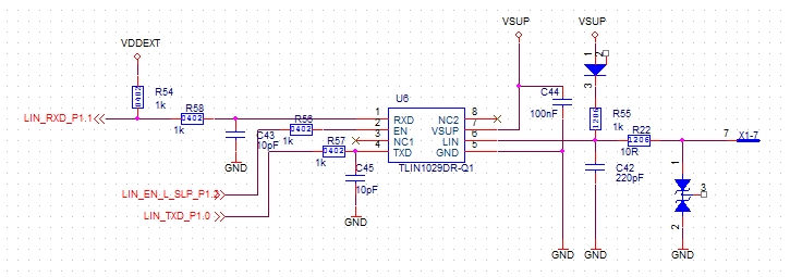
Please review my  schematic of the TLIN1029, there are several problems I need you help check,   

1. What effect does R58 have on the circuit? Can it be added?       

2. If I Remove the R22 during the short-circuit test, will it damage the TLIN1029, what effect will it have without adding this resistor?   

3. What effect C45 has if Put C45 ahead or after R57?

  • Hi Wentao,

    See my comments below:

    1. Series resistors may be placed on digital pins to limit current in the event of an over-voltage condition. This is recommended for the EN and TXD pins. RXD is an open-drain output requiring an external pull-up resistor (R54). In the schematic above, when RXD attempts to pull LOW, a voltage divider created by R54 and R58 will result in a voltage at LIN_RXD_P1.1 near VDDEXT/2. R54 can be moved onto the TLIN side of R58 to avoid this issue. Alternatively, R58 should be a much lower value than R54 (or shorted) in order for LIN_RXD_P1.1 to recognize a LOW.

    2. A small series resistance on the LIN pin helps with transient immunity by limiting the current to the pin. This is good practice but is not necessary to expect data-sheet behavior.

    3. A capacitor placed near the TXD and RXD pins can be used to filter noise. This will have the greatest impact if placed as close as possible to the device.

    Apart from your concerns, I do not see any problems with the schematic. Let me know if you have any questions.

    Regards,

    Eric