This thread has been locked.

If you have a related question, please click the "Ask a related question" button in the top right corner. The newly created question will be automatically linked to this question.

TPS65987D: apply question

Part Number: TPS65987D
Other Parts Discussed in Thread: TPS65982, HD3SS460

Hi TI colleague:

   I have a problem now, our  application type-c as a DFP to supply power external USB and DP display, but after our motherboard is powered on, PP_HV2 has 5V power, Drain2 has 5V power, but VBUS has no power output. The attachment is the firmware I configured. What should I pay attention to here? Is it related to CC detection?What should I pay attention to when configuring firmware?Please help check the configuration information.

TPS65987D tool config.pdf

  • Hello,

    I have taken a look at your configurations however I need a little bit more information to find the cause of this issue. I need to see additional registers, such as the "Transmit Identity Data Object" and the "I/O Config" registers, therefore could you attach the configuration project file to this thread? 

    Also, is the problem that there is no display when you connect the TPS65987D to a monitor? 

    I noticed in the pdf images though that in your "Port Control" register, you have set both of the Swap Strategy fields to reject all swaps. This may be an issue if the monitor is configured to always be a source and the TPS65987D cannot switch to a sink.

    Thank you,

    Hari

  • Hi Hari:

       Thank you for your reply, the attachment is the configuration information and our ciurcuit, please check, thank you.1119 USB-C1.pdftps65987 tool file.rar

  • Hi Hari:

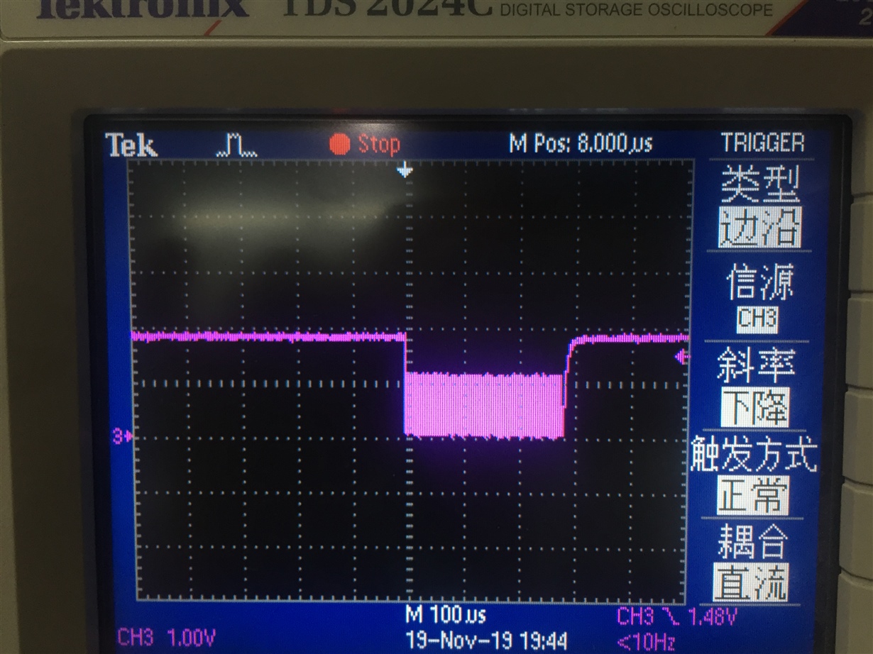
        I have found out why Vbus does not have Power, but according to the firmware of the accessory I provided, insert the TYPE-C HUB,  When the device is plugged in, the waveform of the CC is attached, but when I connect to the USB3.0 device or the DP display, the measured signal is as POL=H EN=L AMSEL=L.,display did not shown.

  • Hello,

    I noticed there were a few DisplayPort settings that weren't configured in your project. For DisplayPort to function properly the configurations must match on the PD controllers. Would you be able to try the configuration project file that I attach here, this should solve the issue.

    TPS65987D Configuration Project: TPS65987DDH_Standard.zip

    If you would like to know more about DisplayPort in detail, I would recommend referring to the DisplayPort Alternate Mode Application Note.

    Thank you,

    Hari

  • Hi Hari:

       When I update the firmware you provided, after inserting the HUB of type-c, Vbus has no output power,and the voltage of Drain2 became 4.5V,  I am still confirming whether the IC is damaged.

  • Hello,

    In that case, I don't think it might be firmware related. The IC may have been damaged if the layout of the circuit isn't setup correctly. I would recommend referencing Section 11, Layout of the datasheet for the schematic example and other layout recommendations such as for thermal dissipation to ensure proper functionality.

    Hari

  • Hi Hari:

        I tried the firmware provided and found that neither USB3.0 nor DP can be used.I checked the firmware configuration you provided and found that the GPIO configuration did not match my schematic ,I modified it myself but still can't.Is it related to communication recognized by CC? We use TYPE-C HUB to access the test function and Windows shows that Displayport connection may not work properly, please try other cables,but i test the POL=L EN=L AMSEL=L.When I pull up 3.3V on POL EN and AMSEL, it is H level after entering the system, it seems that the GPIO is not controlled.

  • Hello,

    Yes, based on the communication from CC, the firmware will trigger the GPIO whenever the event that you have mapped out in the configuration occurs. However, were you able to compare your schematic and layout to the one shown in the datasheet? If it doesn't follow the recommendations that are provided there, your IC may have become damaged.

    Hari

  • Hi Hari:

       Our schematic as attached, the layout is based on the datasheet layout guide. I pull EN and pull down POL and AMSEL according to the table of HD3ss460, so that you can find USB3.0 devices, so the problem point is still firmware and chip. Why accessing 3.0 devices or DP devices, GPIO has no action,the rom we use the winbond w25x10cl,Please help check,I found TPS65982+HD3SS460 GPIO configration as below,so GPIO configration is ok?Can you provide a link to a detailed description of the event .Thanks!

    3056.1119 USB-C1.pdf

  • Hello,

    I noticed that you don't have the GPIO events configured for some of the HD3SS460 Control Pins and therefore the GPIO won't trigger any actions. I would recommend taking a look at Section 3.2 of the DisplayPort Alternate Mode Application Note for configuring this as it shows an example of the GPIO Event Map Register in figure 4. I think this should resolve the issue if the IC isn't damaged.

    Thank you,

    Hari

  • Hi Hari:

        Thanks for your help,now it can be displayed normally。