This thread has been locked.

If you have a related question, please click the "Ask a related question" button in the top right corner. The newly created question will be automatically linked to this question.

DS90UB954-Q1: DS90UB954-Q1 AEQ

Part Number: DS90UB954-Q1
Other Parts Discussed in Thread: ALP

Hi,

I have a 954 connected over 10m of twisted pair cables to 2 x 953.

With some cables I am having trouble getting the link to achieve pass status.

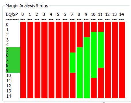
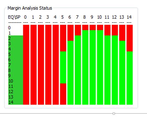
I have compared cables using the Margin Analysis tab in ALP.

For those cables with which there are no issues the MAP shows a large open eye.

For those cables with which there are some problems the eye is less open but easily meets the 'recommended' eye openings in document SNLA301.

When looking at the information page in ALP I sometimes see that the EQ/SP selections are not even showing as green in the eye diagram - yet the values do not seem to be changing as I would expect if the device were hunting for a valid signal.

Resettting AEQ sometimes helps but does not appear to optimise the operating point.

I understand that the first point selected is the first point where the error rate is below the required threshold rather than the center of the eye.

If the performance deteriorates the eye procedure will cause it to move to the next point.

I have a couple of questions:

1.  The app note /datasheet implies that the equalisation algorithm moves in only one direction for each of EQ/SP.  What happens if the algorithm is reaching the extremity of the eye in these directions - is it able to reverse or is it necessary to restart the AEQ?

2.  If the MAP indicates an eye which meets the recommended requirements of SNLA301 - (3 EQ of 4 SP with two contiguous) would it be expected that the link would achieve pass status?

3.  I am using all the default settings wrt AEQ. This means that all EQ levels and 7->10 SP values can be explored.  This certainly covers the green area highlighted in the MAP results.  Is there anything re default settings that I should change?

Can you please advise if this issue appears to be a configuration issue or potentially a genuine cable issue?

Many thanks

Paul

  • Hi Paul,

    1.  The app note /datasheet implies that the equalisation algorithm moves in only one direction for each of EQ/SP.  What happens if the algorithm is reaching the extremity of the eye in these directions - is it able to reverse or is it necessary to restart the AEQ? It restarts the AEQ

    2.  If the MAP indicates an eye which meets the recommended requirements of SNLA301 - (3 EQ of 4 SP with two contiguous) would it be expected that the link would achieve pass status? Yes.

    3.  I am using all the default settings wrt AEQ. This means that all EQ levels and 7->10 SP values can be explored.  This certainly covers the green area highlighted in the MAP results.  Is there anything re default settings that I should change? This will depend on the results. Can you share a screenshot of your margin analysis results?

    Best,

    Jiashow

  • Hi Jiashow,

    Thanks for the reply.  The MAP output for the twisted pair link for which I am seeing the problem is shown

    The typical output for a cable which causes no issues is shown

    Thanks

    Paul

  • Hi Paul,

    The margin looks good. Are you able to get consistent link but just not PASS? How are you setting your PASS criteria?

    Best,

    Jiashow

  • Hi Jiashow,

    I am able to get the link to PASS.  I am successfully passing video frames. 

    However on quite a regular basis I can see the equalisation algorithm is moving to the next equalisation level.  Each time this happens I can see a glitch in the video. 

    Often the error counts in the ALP Information tab continue to read 0, and on other occasions the counts can be non zero.

    The equalisation continues to increase, with a video glitch at each step. It can sometimes take less than 20secs for the AEQ to step through all positions before restarting.

    Can you please confirm/answer the following:

    1.  The equalisation algorithm will not move to the next setting unless errors have been detected in the current setting?

    2.  The errors that are used are those enabled in Reg 0x42 bit[6:4]?

    3.  Do all the enabled thresholds have to be exceeded or just one to cause the equalisation to move to the next setting?

    4.  The MAP analysis of the cable as shown in the previous post shows a significant green area.  Is each setting designated green only if there are no errors detected or are the selections in Reg 0x42 bits[6:4] and the associated thresholds used?

    5.  What causes the AEQ algorithm restart - if the error rate exceeds a pre-determined threshold does the algorithm assume that the eye extremity has been reached and restart?

    6.  Register 0x43 AEQ_ERR_THOLD is described as an error threshold to determine when to re-adapt the EQ settings.  To what errors is this referring and when is this value used?

    7.  Is it correct to assume that all the error counts associated with the FPD links will be affected if the received eye has insufficient opening margin? Is there anything to be gained in trying to differentiate one error from another?

    8.  Is there a way to limit the change to a new EQ/SP setting?  As presently configured it seems that e.g the parity error threshold will always eventually be exceeded.  It might be better to be guided by the error rate.  Is that possible?

    I have a few questions to try and understand the AEQ control Reg and the associated ALP interface

    AEQ control Reg 0x42 gives option of setting three errors for controlling AE algorithm:

    -          FPD Link III Clock Errors

    -          Packet Encoding Errors

    -          Parity Errors

    1.  Can you please let me know what registers are associated with controlling and recording FPD Link III Clock Errors?

    2.  Packet Encoding errors are enabled (Reg 0xB9 bit[4]), threshold set (Reg 0xB9 bits[3:0]) and threshold exceeded detection noted (Reg 0x4E (bit[5]). Is this correct? Is there a register where the current count can be read?

    3.  Parity error counts are recorded (Regs 0x55, 0x56), trigger threshold set (Regs 0x05, 0x06) and threshold exceeded detection noted (reg 0x4D bit[2]). Is this correct?The ALP Information tab, Current RX Port Status window. Provides following counts

    The ALP Information tab, Current RX Port Status window provides following counts

    -          Lock Chg Cnt

    -          Parity Errs

    -          Encoder Errs

    1.  Are the values displayed available in specific registers? Or are these values accumulated by the ALP application – based on successive reads of the associated registers? In my screen at the moment the 3 values displayed are 66, 250399 and 172 respectively. I’m unable to find corresponding values in any registers.

    Thanks

    Paul

  • Hi Paul,

    1.  The equalisation algorithm will not move to the next setting unless errors have been detected in the current setting? That's correct.

    2.  The errors that are used are those enabled in Reg 0x42 bit[6:4]? Correct.

    3.  Do all the enabled thresholds have to be exceeded or just one to cause the equalisation to move to the next setting? Just one.

    4.  The MAP analysis of the cable as shown in the previous post shows a significant green area.  Is each setting designated green only if there are no errors detected or are the selections in Reg 0x42 bits[6:4] and the associated thresholds used? No, MAP analysis checks for Lock, parity, and encoder errors. It's independent of what is set in reg 0x42.

    5.  What causes the AEQ algorithm restart - if the error rate exceeds a pre-determined threshold does the algorithm assume that the eye extremity has been reached and restart? The AEQ algorithm resets and restart once it reachs the highest EQ/strobe position.

    6.  Register 0x43 AEQ_ERR_THOLD is described as an error threshold to determine when to re-adapt the EQ settings.  To what errors is this referring and when is this value used? Any of the errors set in the AEQ control register.

    7.  Is it correct to assume that all the error counts associated with the FPD links will be affected if the received eye has insufficient opening margin? Is there anything to be gained in trying to differentiate one error from another? To the user, if any errors occur, that means the link is unstable. It doesn't matter if it's lock drop, parity, or encoder errors. While lock drop is the most severe, parity errors in the system shouldn't be ignored. The smaller the eye diagram is, the smaller your margin will become.

    8.  Is there a way to limit the change to a new EQ/SP setting?  As presently configured it seems that e.g the parity error threshold will always eventually be exceeded.  It might be better to be guided by the error rate.  Is that possible? Errors are measured over a period of time equal to ½ of the value specified by the ADAPTIVE_EQ_RELOCK_TIME (reg 0xD2) field. If the number of errors is greater than the programmed threshold in the AEQ_ERR_THOLD register, the EQ setting will be invalid and the AEQ will continue with the next setting.


    I have a few questions to try and understand the AEQ control Reg and the associated ALP interface

    AEQ control Reg 0x42 gives option of setting three errors for controlling AE algorithm:

    -          FPD Link III Clock Errors

    -          Packet Encoding Errors

    -          Parity Errors

    1.  Can you please let me know what registers are associated with controlling and recording FPD Link III Clock Errors? To put it simply, the serializer sends a sequence of values to the deserializer so that the deserializer can lock to the serializer. If clock and encoder errors occur, then this means the deserializer is having issues locking to the serializer. There's no registers to control the clock errors, it'll simply show as lock drop.

    2.  Packet Encoding errors are enabled (Reg 0xB9 bit[4]), threshold set (Reg 0xB9 bits[3:0]) and threshold exceeded detection noted (Reg 0x4E (bit[5]). Is this correct? Is there a register where the current count can be read? No, but as I explained in the previous question, usually when encoder errors occur, lock will drop.

    3.  Parity error counts are recorded (Regs 0x55, 0x56), trigger threshold set (Regs 0x05, 0x06) and threshold exceeded detection noted (reg 0x4D bit[2]). Is this correct?The ALP Information tab, Current RX Port Status window. Provides following counts. Yes.


    The ALP Information tab, Current RX Port Status window provides following counts

    -          Lock Chg Cnt

    -          Parity Errs

    -          Encoder Errs

    1.  Are the values displayed available in specific registers? Or are these values accumulated by the ALP application – based on successive reads of the associated registers? In my screen at the moment the 3 values displayed are 66, 250399 and 172 respectively. I’m unable to find corresponding values in any registers. Lock change and encoder are accumlated by ALP. Parity errors can be read in reg 0x55 and 0x56.