This thread has been locked.

If you have a related question, please click the "Ask a related question" button in the top right corner. The newly created question will be automatically linked to this question.

DP83867IR: Packet "Dead Zones"

Part Number: DP83867IR

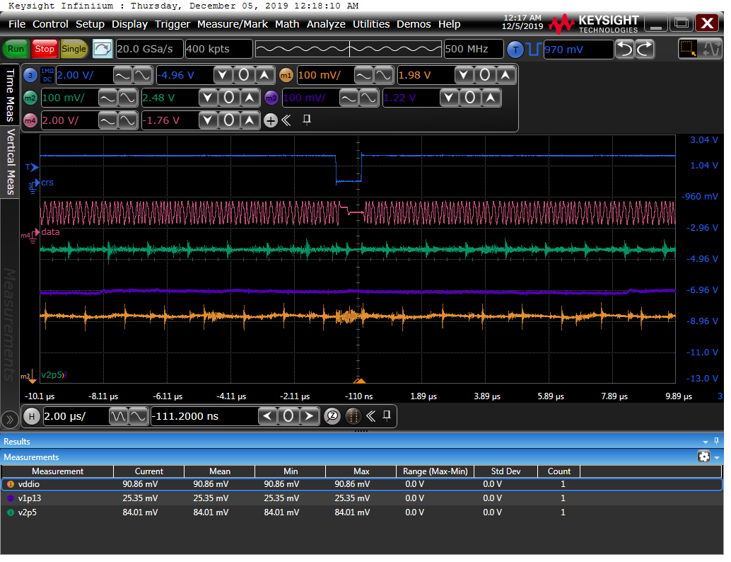
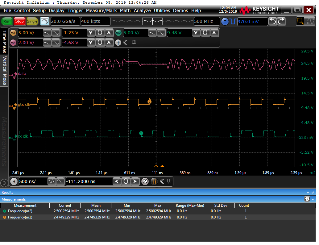
I am experiencing a data dead zone on Channel A from the phy to magnetics. Using a large data payload these dead zones will appear at uniform intervals of 80 us.  The data stops for  800 ns then continues.  Because this is so repeatable and the stop and restart looks identical from board to board or packet to packet there seems to be a mechanism within the device that is being tripped.

  • Hello Brian,

    Can you give me more details about the mode you are using and information about your setup?

    What pins are you probing for this waveform?

    Thanks,

    Vibhu

  • Hi Vibhu,

    The DP83867IRPAPR is in RGMII mode with a host PC set at 10 Mbps. 

    The host is sending data to pins 5 & 6 of the DP83867 and waveform is the return data from pins 2 & 3.

    Here is what the status registers poll at power up:

    Start PHY autonegotiation
    Waiting for PHY to complete autonegotiation.
    autonegotiation complete
    Register BMCR (0x0000) is FFFF1140
    Register PHY_STS(0x0011) is FFFF3C02
    Register PHY_TI_STRAP1 (0x06E) is FFFF000D
    Register PHY_TI_STRAP1 (0x006F) is FFFF0000
    Register PHY_RGMIIDCTL (0x0086) is FFFF00C6
    link speed for phy address 13: 10
    Configuring default IP 192.168.1.10
    Board IP: 192.168.1.10
    Netmask : 255.255.255.0
    Gateway : 192.168.1.1

  • I also discovered that pin 56, CRS is synced with the data interruption.  

    -----lwIP RAW Mode TCP Client Application-----
    Start PHY autonegotiation
    Waiting for PHY to complete autonegotiation.
    autonegotiation complete
    Register BMCR (0x0000) is FFFF1140
    Register PHY_STS(0x0011) is FFFF3F02
    Register PHY_TI_STRAP1 (0x06E) is FFFF000D
    Register PHY_TI_STRAP1 (0x006F) is FFFF0000
    Register PHY_RGMIICTL (0x0032) is FFFF00D3
    Register PHY_RGMIIDCTL (0x0086) is FFFF00C6
    link speed for phy address 13: 10
    Configuring default IP 192.168.1.10
    Board IP: 192.168.1.10
    Netmask : 255.255.255.0
    Gateway : 192.168.1.1

    TCP client connecting to 192.168.1.100 on port 5001
    On Host: Run $iperf -s -i 5 -w 2M

  • Hello Brian,

    Please check the GTX_CLK and RX_CLK during the dead zones as well to see if they are still running at 2.5 MHz.

    The CRS pin is not used in the RGMII mode of operation.

    Can you also send me a zoomed in picture of the voltage levels during normal operation and right before the dead zone? Compare the voltages with the MDI voltage listed under "7.5 Electrical Characteristics".

    How did you determine your RGMII delay values?

    It looks like between the two setups you've posted the link was resolved as MDI once and MDIX the other time. Was this intentional?

    Thanks,

    Vibhu

  • The MDI vs MDIX is not intentional and is probably indicative of a problem as the board(s) are strapped the same. RX Clock, GTX Clock, & TX Data lines are active during the dead zone.  

  • Thank you Vibhu,

    The TX Clock being so far off revealed an issue with the system clock being slightly off frequency.  The problem was easy to overlook since other functions like SD card, terminal, I2C were each working fine.