This thread has been locked.

If you have a related question, please click the "Ask a related question" button in the top right corner. The newly created question will be automatically linked to this question.

DP83822IF: waveform of the idle 0x55 code Question

Part Number: DP83822IF

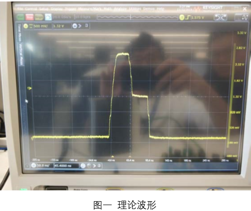
In the Ethernet physical layer consistency test, there is a problem: under normal test conditions, the waveform of the idle 0x55 code mtl-3 of 100base TX should be as shown in Figure 1, but we found that the waveform is as shown in Figure 2, which is similar to a 10base waveform.

After finding some solutions on the Internet, Rx ﹣ D3 Rx ﹣ D2 Rx ﹣ D1 Rx ﹣ d0 pins are all equipped with pull-up resistance, an ﹣ 0 pin is pulled high, and configured into full duplex, self negotiation mode. But the waveform of Figure 2 is still measured.

Questions to be answered:

Is the waveform in Figure 2 because the auto negotiation function is turned on?

Do we need to turn off the auto negotiation function to get the waveform in Figure 1?

If our judgment direction (turn off auto negotiation) is correct? To turn off auto negotiation, which parts of dp83822ifrhbr need to be processed on the hardware?

If it is shut down by software, what kind of operation is it?


  • Hi HY,

    Yes you see the waveform in Figure 2 is because Auto-Negotiation is on. You can turn off Auto-Negotiation and force 100 Mbps speed by setting Register 0 to 2100. If you would rather use hardware straps to force 100 Mbps speed, please review section 8.5 and Table 12 of the datasheet for the proper configuration. 

    Thank you,

    Nikhil

  • Thank you. With your support, we have tested the PMD waveform.

    But there are two questions:

    1) the configuration in the test is to set an [en] to 0 (that is, RX [D3] is pulled high in mode 2 or Mode3), turn off the auto negotiation function. After the auto negotiation function is turned off, although PMD waveform can be obtained, TwinCAT cannot scan to the EtherCAT slave station (et1100 is connected with dp83822).

    2) we compared the waveform of Panasonic A6 servo driver (PHY chip is ksz8041nl). We would like to know if dp83822if can be configured with the same coding waveform? If so, how do we configure dp83822?

  • Hi HY,

    The KSZ8041 is 10Base-T while the DP83822 is 10Base-Te, so the waveforms may look different and may not be the source of an issue. 10Base-T and 10Base-Te will inter-operate with each other and will be able to successfully Auto-Negotiate. What exactly are the issues you are seeing?

  • Thank your for your relpy.

    I am the questioner's partner.I'd like to repeat the question for clearer expression.We are now developping a servo driver control board with EtherCAT communication, using DP83822IF as the physical layer device to connect with ET1100. The PHY connection on the schematic refers to the  TI document "Ethercat Interface for High Performance MCU Schematic (Rev.A)".  The actual connection is shown in Figure 1.

                                                                                                       Figure 1


    Then we use Keysight DSOV084A oscilloscope to do the physical layer conformance test  of 100BASE-TX standard.
    But we captured waveform shown in fig. 2.  This waveform cannot be tested.

    The first question is this the 10BASE-Te waveform?  According to the schematic , the connection has already started the auto-negotiation function. Why it can't  automatically negotiate to 100M full duplex Mode?

    Fig. 2 captured waveforms in auto-negotiation mode

    According to the description on Datasheet, we configured PHY chip forced to 100BASE-TX,Full-Duplex mode, and auto-negotiation function is turned off.  The specific Strap resistor configuration is shown in Table 1.

                                                    Table 1 Strap Resistor Configuration

    Pin

    Mode

    Function

    COL

    4

    FX_EN

    PHY_AD0

    0

    1

    RX_D0

    1

    AN_1

    PHY_AD1

    1

    0

    RX_D1

    1

    EEE_EN

    PHY_AD2

    0

    0

    RX_D2

    4

    FLD_EN

    PHY_AD3

    0

    1

    RX_D3

    2

    AN_EN

    PHY_AD4

    0

    0

    LED_0

    4

    reserved

    AN_0

    1

                                                                                     Fig. 4 waveform captured in forced mode

    Then the waveform captured can passed the test , but there is a problem, EtherCAT master (TwinCAT) could not scan to the slave (ET1100).
    This is our second question: Why turn off auto-negotiation cause EtherCAT master can not to recognize slave?

    Setting AN_EN to 0 (i.e. RX_D3 in MODE 2 or MODE3) ,turn off the auto-negotiation function and pass the physical layer consistency test, but the master cannot recognize the slave .
    Setting AN_EN to 1 (i.e. RX_D3 is in MODE 1 or MODE4) ,turn on the auto-negotiation function. the master can recognize the slave ,but cannot pass the physical layer consistency test.

    So,what we are looking for help is how to configure PHY to enable EtherCAT slave to be recognized normally and pass the consistency test of physical layer at the same time. 

    We compared the waveform of Panasonic MBDLN25BE servo driver (PHY chip is KSZ8041NL). According to your reply, this is the 10BASE-T waveform, but it passed the consistency test of 100BASE-TX.

                                                              Figure 5 Comparison of Test Waveforms of Panasonic A6 Servo Driver

  • Hello,

    For compliance testing, please review TI App Note SNLA266 linked here: http://www.ti.com/lit/an/snla266/snla266.pdf. Compliance testing requires forced modes, it cannot be completed under auto-negotiation, which is why you may be running into issues. The app note details the correct register writes for each test. You may leave the PHY in it's default state when following these steps. Please let me know if you are still running into issues.

    Thank you,

    Nikhil