Other Parts Discussed in Thread: DS90UB960-Q1, TIDA-020002, , ALP
Hi TI team,
My customer has the following problems, which are described in Chinese. I am not familiar with SerDes products. I translate the questions from Chinese to English. If you are confused, please point out.
Currently, ti960 / ti953 / and imx390 can be accessed through I2C (the correct signal of I2C at the sensor end can be measured)
Hardware:
POC filter; refer to ds90ub960-q1 figure 40. Typical POC network for a "4G" FPD link III
REFCLK: 25Mhz ( 100ppm)
Mode : Strap Configuration Mode Select; No.4 of Table2. /CSI-2 Mode
Set up:
Roughly refer to design guide: tida-020002
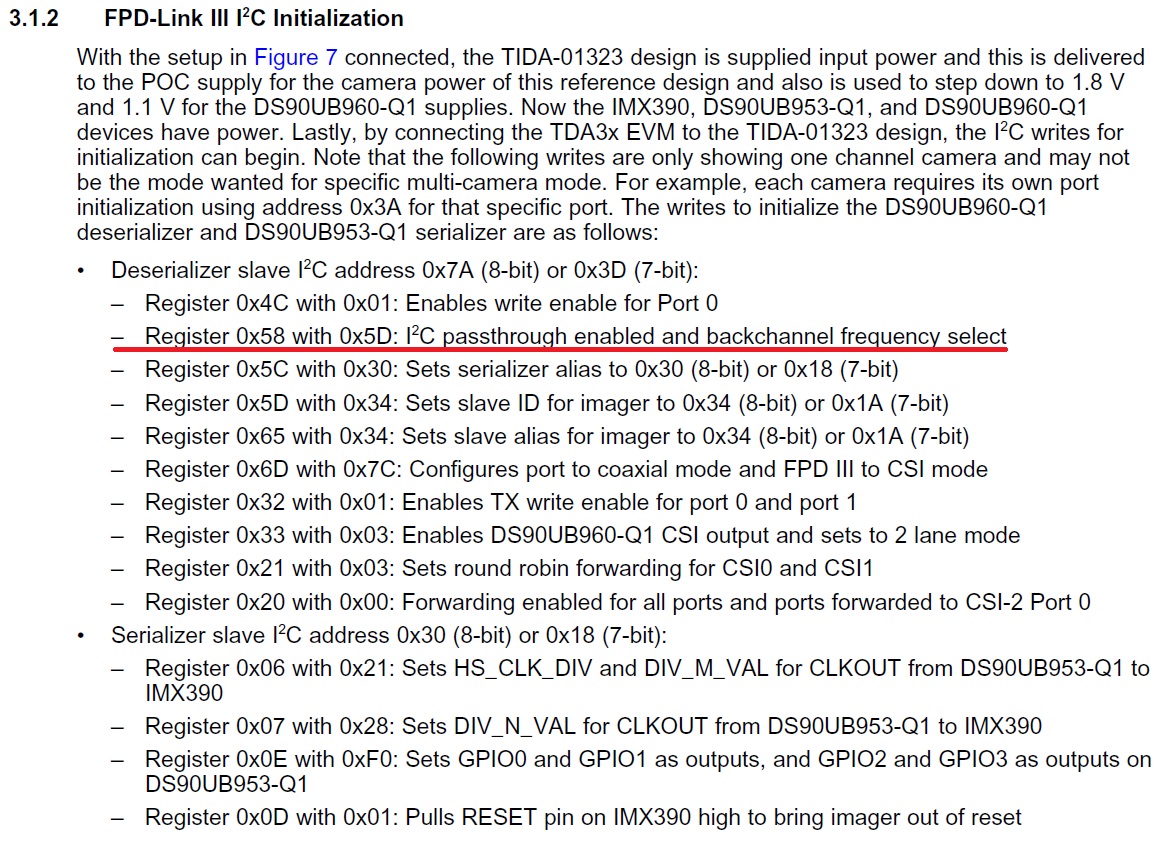
FPD-Link III I2C Initialization
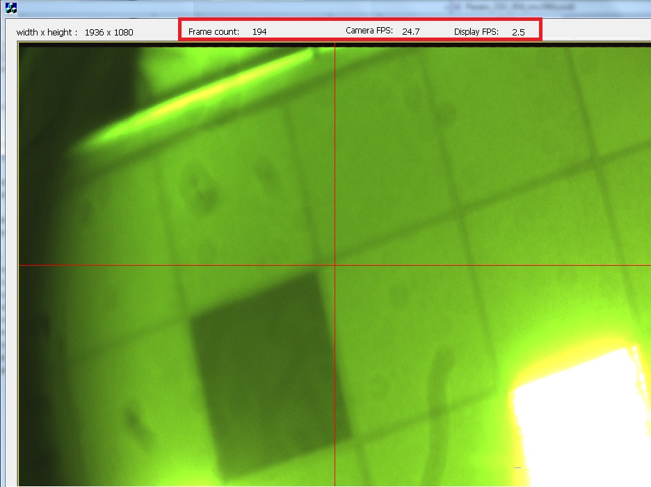
But csi0 output MIPI signal is intermittent. There is no way to output a complete image.
It is found that the setting may be discontinuous
Register 0x33 with 0x01: without Enable CSI-2 continuous clock mode.
But it was found in the documents
Ds90ub953-q1 page 17, csi-2 is divided into short and long packet (including VC / Data ID...) how to confirm or set the output short packet?
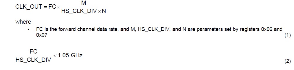
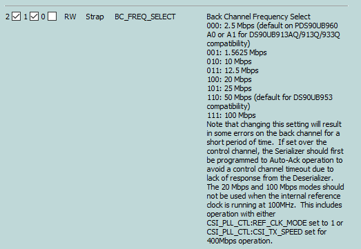
In addition, ds90ub953-q1 modifies Reg 0x06/ 07 CSI0 to output MIPI, which seems to have an impact, but how to adjust it correctly??
Best Regards,
Amy Luo