This thread has been locked.

If you have a related question, please click the "Ask a related question" button in the top right corner. The newly created question will be automatically linked to this question.

TCA9548A: Doubt about addressing

Part Number: TCA9548A

Dear TI team,

I am interested in using TCA9548A to implement a I2C network as follows:

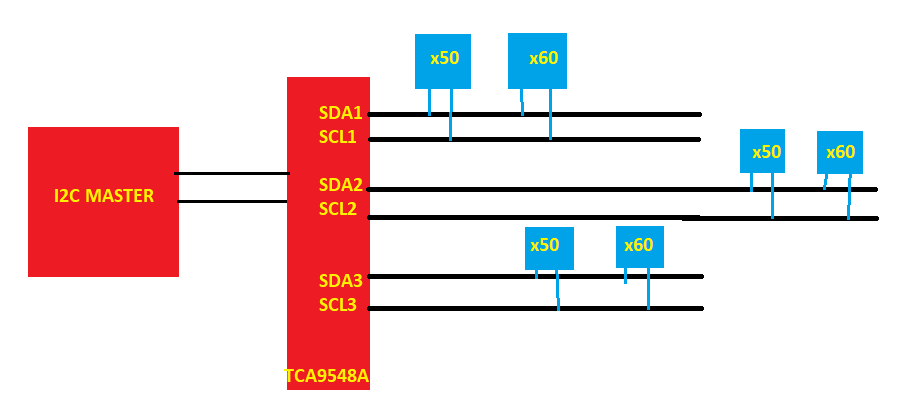
As you can see, we have i2C devices with the same address. I think it is possible to address I2C devices with the same address through the TCA9548A switch. 

As far as I understand the address is composed of the mux (TCA9548) address + the channel address: 

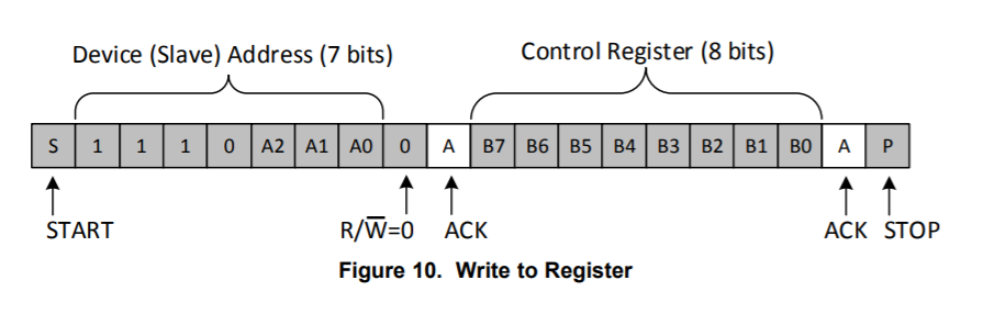
But I don´t understand how finally the I2C device is reached. Where is added the address information of the I2C slave device? How the I2C master is able to address the I2C slave device when several devices are connected to the same channel?

  • Hi Manuel,

    TCA9548A can indeed be used to avoid address conflicts in an I2C system. However, I think you're a bit confused on how to interface with the device from a Master point of view. 

    TCA9548A acts as a slave device itself. The device manages which parts of the I2C bus are connected to the Master SDA/SCL. Like other I2C slaves, it only handles information that is addressed specifically for it. The master can write to the TCA9548A's control register by sending a packet with the switch's (slave) Address followed by the desired value of the Control Register. This process is depicted in Figure 10 (in original post). TCA9548A will then switch which pins are connected to the Master side of the I2C bus. Now a separate command can be sent to a slave device on the newly connected bus. Because the new command is not addressed to the TCA9548A, the switch will ignore it. However, because we previously connected a new section of the bus, a slave on the other side will recognize its address and be able to communicate accordingly. 

    For example, in your figure above, if we wanted to read the slave addressed '0x05' on the bus SDA1/SCL1, first we would have our master write to the TCA9548A. The write will contain the Address (0x70 - 0x077 depending on A2 - A0) and desired Control Register value 0x02 (bit 1 to enable SDA1/SCL1). Now that TCA9548A has switched on this bus, we can send a read command to our slave addressed '0x05'. If we desire to read the next slave down on SDA2/SCL2, we would first write 0x04 to TCA9548A's Control Register to enable SDA2/SCL2 while also disabling SDA1/SCL1.

    Let me know if this explanation makes sense or if you have any more questions.

    Regards,

    Eric

  • Hello Eric,

    thanks a lot for your feedback. Now the operation is clear for me.