This thread has been locked.

If you have a related question, please click the "Ask a related question" button in the top right corner. The newly created question will be automatically linked to this question.

SN65DSI86: Qualcomm SDM450 / SN65DSI86 eDP panel training fail

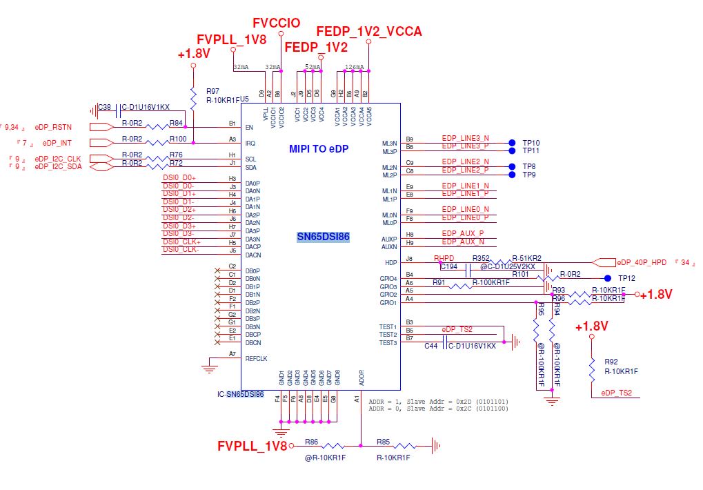
Part Number: SN65DSI86
Other Parts Discussed in Thread: TEST2

Hi 

We have SN65DSI86 on Qualcomm SDM450 platform, and try to enable AUO B140XTN02.E but fail.

Have search support forum and try all of suggestion that found here, but still no luck.

Our enable process are:

regmap_write(pdata->regmap, 0xFF, 0x07); // switch to Page 7
regmap_write(pdata->regmap, 0x16, 0x01); // set ASSR_CONTROL writable
regmap_write(pdata->regmap, 0xFF, 0x00); // switch to Page 0
regmap_write(pdata->regmap, 0x0A, 0x03); // REFCLK_FREQ, 384 MHz
regmap_write(pdata->regmap, 0x10, 0x26); // CHA + 4 Lanes
regmap_write(pdata->regmap, 0x5C, 0x01); // disable HPD input
regmap_write(pdata->regmap, 0x12, 0x4C); // CHA DSI CLK Range: 384 MHz
regmap_write(pdata->regmap, 0x94, 0x80); // 2.7 Gbps HBR, Swing Level 0
regmap_write(pdata->regmap, 0x0D, 0x01); // PLL Enable
// check DP_PLL_LOCK succeed
/* 0x64~0x73 AUX_WDATA0 through AUX_WDATA15 => Disable ASSR mode */
regmap_write(pdata->regmap, 0x74, 0x00); //AUX_ADDR[19:16]
regmap_write(pdata->regmap, 0x75, 0x01); //AUX_ADDR[15:8]
regmap_write(pdata->regmap, 0x76, 0x0A); //AUX_ADDR[7:0]
regmap_write(pdata->regmap, 0x77, 0x01); //AUX_LENGTH
regmap_write(pdata->regmap, 0x78, 0x81); //AUX_CMD
mdelay(10);
regmap_write(pdata->regmap, 0x93, 0x24); // 2 DP Lanes
regmap_write(pdata->regmap, 0x96, 0x0A); // Start Semi-Auto Link Training
// check 0x96 ML_TX_MODE_REG

but we always can't not pass Semi-Auto link, the status always indicate main link off.

The error registry dump show as below

sn65dsi86_dump_err_reg()
0xF0h = 0x00
0xF1h = 0x00
0xF2h = 0x00
0xF3h = 0x00
0xF4h = 0x08
0xF5h = 0x00
0xF6h = 0x00
0xF7h = 0x00
0xF8h = 0x02

We have try:

1. force force ML_TX normal, but no data display on screen.

2. try others training mode TPS1, TPS2, and etc, but only fast link can pass, but still no data display on screen.

3. adjust VOD level, swing level, but still no pas training.

4. using PANEL_VIDEOREGISTER_CALC.xlsm to fill up EDID data from panel datasheet, but still not help.

5. ignore training, just enable color bar test pattern, but no data display on screen.

Have any suggestion that we can try? Thanks.

Rick

  • Rick

    Do you have TEST2 pin pulled high?

    Would you please send me the schematic and panel EDID info?

    Thanks

    David 

  • Hi David
    Yes, we have TEST2 pin pulled high.
    The schematic as attachment.
    Rick
  • Hi David
    Yes, we have TEST2 ping pulled high.
    The schematic as attachment.
    Rick
  • And We have extra board to connect between SN65DSI86 and eDP panel. The schematic also attached below.

    The board is working with panel working on our another platform (Intel CherryTrail eDP output).

  • Rick

    You have EMI on both the DSI86 part of the schematic and the eDP board, have you tried to remove the extra EMI components?

    Have you verified the DP lane order is correct? DSI86 lane 0 is connected to the eDP panel lane 0, and DSI86 lane 1 is connected to eDP panel lane 1?

    Could you please check to make sure HPD is driven high?

    Can you please send me the panel EDID info?

    Thanks

    David

  • Hi David
    The EMI components is removed (reserve for EMI only). 
    And HPD pull-high is must? or can be ignore by disable HPD detect?
    regmap_write(pdata->regmap, 0x5C, 0x01); // disable HPD input
    The panel EDID info as attachment.
    Rick
  • Rick

    What is your DSI_CLK frequency?

    Please note when using the REFCLK as the clock source, any DSI Clock frequency is supported, but if the clock source was instead the DSI A clock, then the required DSI Clock frequency would need to change to a frequency supported by the DSI86. When operating in this mode, any one of the following DSI A clock frequencies can be used: 384 MHz, 416 MHz, 460.8 MHz, 468 MHz, or 486 MHz.

    Thanks

    David

  • Hi David

    We have used sllu204_EVM to verify this AUO panel; we connect I2C with Qualcomm SoC with EVM only, and let panel to connect on EVM.

    Using same test code to enable this panel, but the training process still fail. The error showing maximum VOD reached, what value that we should change to fix this problem?

    [ 35.505341] sn65dsi86_dump_err_reg()
    [ 35.505900] 0xF0h = 0x00
    [ 35.508503] 0xF1h = 0x00
    [ 35.511185] 0xF2h = 0x00
    [ 35.513692] 0xF3h = 0x00
    [ 35.516147] 0xF4h = 0x00
    [ 35.518662] 0xF5h = 0x00
    [ 35.521262] 0xF6h = 0x00
    [ 35.523699] 0xF7h = 0x00
    [ 35.526221] 0xF8h = 0x0e

  • Rick

    If the same code works on the EVM, then we need to look at the hardware difference between the two designs.

    What is your DSI_CLK frequency, are you using a DSI_CLK frequency that is supported by the DSI86?

    Please note when using the REFCLK as the clock source, any DSI Clock frequency is supported, but if the clock source was instead the DSI A clock, then the required DSI Clock frequency would need to change to a frequency supported by the DSI86. When operating in this mode, any one of the following DSI A clock frequencies can be used: 384 MHz, 416 MHz, 460.8 MHz, 468 MHz, or 486 MHz.

    Thanks

    David

  • Hi

    The SW2 DIPSW configuration is as below:

    ---- 27 MHz REFCLK

    GPIO1 - low

    GPIO2 - low

    GPIO3 - high

    GPIO4 - low

    ---- ADDR 0x2C

    ADDR - low

    ----- Disable ASSR

    TEST1 - high

    TEST2 - high

    And the SoC side, the DSI clock is 225MHz.

    Currently we want to verify the EVM can enable this AUO B140XTN02.E eDP panel only (with color bar pattern), but still can't pass Semi-Auto Link Training, and no test pattern display on panel. Does AUX training is must pass for eDP panel? or we can ignore it? 

    Rick

  • Rick

    DSI86 supports fast link training. Prior knowledge of the calibrated settings is required in order to use Fast Link Train. SW needs to program both the DSIx6 and the eDP panel with the calibrated settings. Once this is done, software can change the ML_TX_MODE from Main Link Off to Fast Link Training. The DSIx6 will transmit the enabled TPS1 and/or TPS2 pattern and then transition the ML_TX_MODE to Normal Mode.

    Any chance you can send me the panel?

    Thanks

    David

  • Rick

    Did you also check to make sure the physical connection between the EVM and the panel is correct, lane 0 goes to lane 0, lane 1 goes to lane 1, etc?

    Thanks

    David