This thread has been locked.

If you have a related question, please click the "Ask a related question" button in the top right corner. The newly created question will be automatically linked to this question.

DP83848I: DP83848I getting Hot

Part Number: DP83848I

Hi,

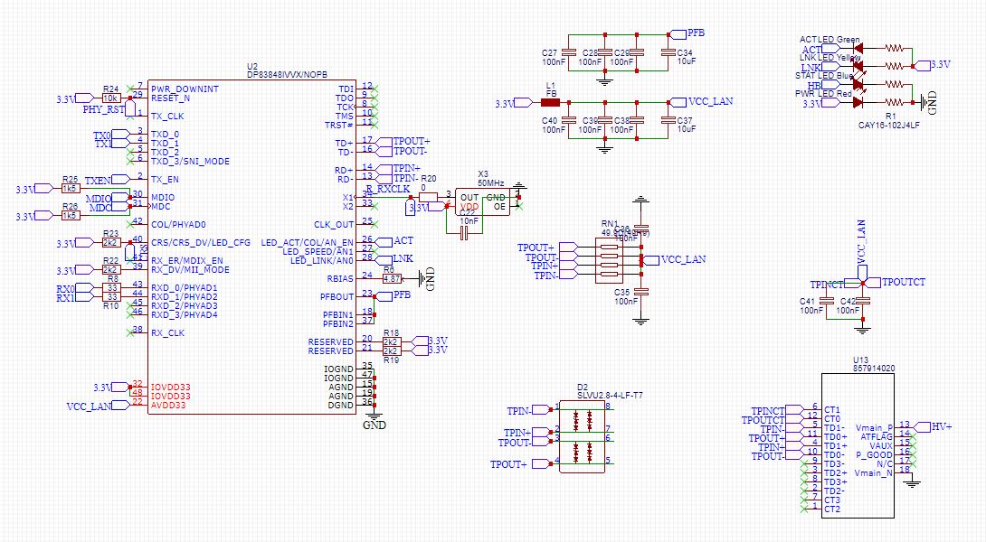
I have a board with DP83848I that we have made that appears to be getting hotter than expected. The board is powered off POE power with a LM5166YDRCR 3.3v regulator. this powers the MCU without any issues and appears to be very stable running a STM32F407VET without the MCU getting warm. The network connectivity works and functions as it should except the PHY is getting hot. When we run the board from a usb to Serial board with a 3.3v feed it appears to run a lot cooler over this than the POE. But it sill appears to be warmer than expected. I have a Dev board with the same MCU and PHY and the PHY does not get warm at all on Serial power. It would be appreciated if someone could provide some feedback on what maybe cause 
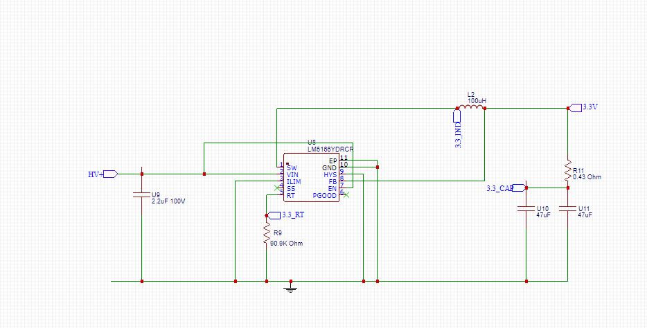
ing the PHY to get hot. 

  • Hello Chris,

    Here are my comments on the schematic:

    • MDC does not require a pull-up
    • The center taps of the magnetics need to be grounded to GND and earth GND on either side of the magnetics
    • Please double check the power-feedback cap placement based on section "7.2.1.3 Power Feedback Circuit

    Are you able to isolate what component makes the board hot? Sorry it was a bit unclear to me whether it was the regulator, MCU or PHY that you suspect is causing the issue?

    Are you able to measure the power consumption of the isolated PHY?

    Thanks,

    Vibhu

  • Hi Vibhu

    Thank you for your prompt response, just following up on the above points you made. 

    • MDC does not require pullup - This has now been removed and has made no affect to the temp 
    • Center taps of the magnetics to ground - Are you sure that this is correct to ground? the datasheet of the DP83848 says that this should be pulled to VDD and place capacitor close to the center taps. ( currently 0.700mm from TPOUTCT)
    •  Feedback cap placement - The Caps for these are placed 1.78mm from the PHY 

    It has been hard to try and isolate what components make the board hot as it is on a printed circuit board. The rest of the board and components do not get hot at all including the regulator and MCU. It appears to only be the PHY that is getting hot and affected. I will attempt to see if I can measure the current of the PHY and let you know.

    Any further assistance would greatly be appreciated.

    Kind Regards

    Chris

  • Hello Chris,

    I apologize, you are correct about the center taps please follow "Figure 7-2. 10/100 Mb/s Twisted Pair Interface".

    Please let me know if you have been able to take the current measurement.

    Thanks,

    Vibhu

  • Hi Vibhu,

    I'm Aaron and work with Chris.

    I have measured the current draw at the point noted below in green and found when running from an external 3.3V source it measures 95.8mA with minimal heat. When running on PoE (on-board regulator) it draws 98.9mA and heats up. 

    Unfortunately I'm unable to measure the exact temperature without a temp gun.

    Out of curiosity, is it necessary to have a power source that's electrically isolated from the PoE source? I'm not sure if the below schematic (from the mag-jack) sheds any light on the subject?

    Kind regards,

    Aaron

  • Hi Aaron,

    Apologies on the delay. I will be taking over this E2E thread now. Have you measured what the current looks at the 3.3V net? I'm having trouble understanding where the source of the heat is coming from if both are supplying about 95mA

    Also i may have missed this link but where exactly is this diagram of the POE and Ethernet from? I would like to read from the entire document.

    Thanks,

    Cecilia

  • Hi Cecilia,

    Thanks for looking into this. Unfortunately due to the board design, it's not practical to measure from the 3.3V net. I could however measure the draw of the entire board if that's of interest? The next design will have a 0 Ohm resistor for each group of components for testing purposes. Did there appear to be any issues with the schematics?

    The PoE schematic comes from the RJ45 socket we're using with built in PoE. Please see product details here: https://www.molex.com/molex/products/datasheet.jsp?part=active/0857914020_MODULAR_JACKS_PLUG.xml

    Original designs used the ENC28J60 with no heat issues, but was limited in functionality, so the LAN8720 was tested next. This is when the PHY heat issues began. Assuming the cause was due to design with conflicting documentation and examples, we are now utilising the DP83848. Unfortunately the heat issue is still present. The original prototype with the ENC28J60 has been running for over a year (24/7) without an issue, so believe the power circuitry to be fine, but didn't know if the DP83848 had more stringent requirements.

    We have purchased other testing boards with the DP83848 which don't appear to heat up at all. These boards don't appear to follow the placement requirements as stringently as we have, yet we still have the issue.

    Your assistance in this is greatly appreciated.


    Kind regards,

    Aaron

  • Hi Cecilia,

    I've noticed something else peculiar with the heat of the chip. It seems to not heat up until the network cable is plugged in (running from an external power source). Once the network cable is unplugged in again, the chip cools down. it doesn't seem to matter whether using a PoE port from the switch or not. I'm not sure if this helps or is a red herring.

    Also wondering if the schematics sent through is enough info, or if you require the full set?

    Kind regards,

  • Hi Aaron,

    Apologies for the delay during the holiday seasons. I will be following up with your request today. 

  • Hi Aaron,

    Just to summarize: the PoE port may not be the source of the heat issue but perhaps the network cable now, correct? By network cable (running from external source) do you mean when you are connecting the cable at U13 you are now using an external supply and not the POE port? 

    Is the switch also conducting heat when this occurs and how is it being powered externally?

    Just wanted to cover my bases so we can isolate this further. 

    Thanks

    Cecilia

  • Hi Cecilia,

    When the ethernat cable is plugged in to U13, the heat issue starts. This is regardless it is powered by PoE, or by an external power source. The external power souce is via a 3.3V linear regulator.

    I'm not sure what you mean by "Is the switch also conducting heat". The network switch is running as it normally does and not reporting any issues.

    On the protoype board, the only component experiencing heat more than 10 deg C above ambient it the PHY chip. MCU, Regulators, flash, magjack, etc are all cool.

    Kind regards,

  • Do you have an image of your layout/routing you can share of the PHY? I'm wondering if the thermal pad was grounded properly to dissipate all the heat on the chip.

    Thanks,

    Cecilia

  • Hi Cecilia,

    The DP83848I doesn't have a grounding / heat sink pad, but happy to show you the layout. I'm currently out of the office but will forward it as soon at possible.

    Kind regards,

  • Hi Aaron,

    Not a problem. Please provide the layout at your most convenient time.

    Thanks,

    Cecilia

  • Hi Cecilia,

    Please see below for partial board layout. As this is a public forum, I'd prefer not to show the whole design. Happy to forward a copy in private if you can advise of where to send it.

  • Hi Aaron,

    For your LEDs on your schematic: 

    • Were you intending on strapping the pins or are the straps on a different page of your schematic?
    • What are the resistor values and current limit on the LEDs? 
    • Could you perhaps remove the resistors and see if the LEDs are sinking current causing the thermal issue?

  • Hi Cecilia,

    Sorry for the delay in my response.

    • I wasn't intending on other strapping, however have also tried pulling the floating rx pins low (via a 2k2 resistor each) without it making a difference.
    • The resistor values on the LEDs are all 1k. Forward voltage is 1.8V and forward current is 20mA.
    • I'll remove the resistors and let you know if there is a difference.

    Kind regards,

  • Hi Cecilia,

    I have now removed both the LEDs, however it doesn't seem to have made any difference.

    Can you please let me know what temp I should be expecting on the PHY chip?

    • Room temp - 24 deg C
    • Auto speed and duplex negotiating at 100 Full

    Kind regards,

  • Hi Aaron,

    You can find our recommended operating conditions and thermal information in Section 5.3 and 5.4 of our datasheet.

    Thanks,

    Cecilia