This thread has been locked.

If you have a related question, please click the "Ask a related question" button in the top right corner. The newly created question will be automatically linked to this question.

DS90UB954-Q1: PLL signal and Lock time

Part Number: DS90UB954-Q1

Dear support team;

I have 2 questions.

1) PLL Lock Time

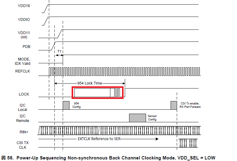
On datasheet, PLL lock time is defined the following time with DS90UB954-Q1.

But, I think that this value is not default register setting.

Could you tell me the maximum and typical lock time when using default register value?

2) Lock signal

I think that LOCK signal is Lo continuously while the following red term.

Or LOCK signal is unstable(Hi and Lo)?

Because, I would like to check the LOCK status by using MCU interrupt via LOCK signal.

How do you think?

B.R

 Masaaki Sugiyama

  • Hello Masaaki-san,

    1) LOCK time with the default value may be a bit longer than what is listed in the datasheet, but it is recommended to use the value 0xA9 instead of 0xA7 for the S-Filter. Exact numbers are not available unfortunately.

    2) Yes, you may have multiple Locks and unlocks before you have the final stable Lock. 

  • Dear Hamzeh-san;

    Thank you for your reply.

    1) When I set the following value, do you have the maximum and typical lock time?

     0x41 SFILTER_CFG = 0xA9

     0xD5 AEQ_MIN_MAX = 0xF2 (default value)

    2) You mentioned "yes".

     Does this mean unstable in the red frame period?

     Of course, it is assumed that FPD-Link signals are continuously stable in the red frame period.

    B.R

     Masaaki Sugiyama

  • 1) I am not sure if you are using short or long cable. If shorter cable then I recommend you change register 0xD5 to 0xF0.

    If you do this, i.e. use the recommended settings then the typical or max LOCK times are exactly the given numbers in the datasheet.

    2) in the red box it is okay to have unstable LOCK. This is the max. LOCK time mentioned in #1.

  • Dear Hamzeh-san;

    Sorry, additional questions.

    1) Lock time

     I think that when I set the 0x41: SFILTER_CFG = 0xA9 and  0xD5:AEQ_MIN_MAX = 0xF2, pll lock time is shorter than 300 ms.

     Is this correct?

    2) Lock signal status

    My expectation is that the lock signal is continuously “0” until it reaches pll lock state.

    For example, when AEQ is full range and SFILTER_CFG=0x9A, lock signal is the following waveform.

    Is this correct?

    B.R

     Masaaki Sugiyama

  • Hello Masaaki-san,

    1) Yes, if you have 0xA9 and 0xF2 then Lock time will be shorter than 300ms. But as I said, if you have shorter cable (1-3 meter) I recommend you change the value of 0xD5 from 0xF2 to 0xF0.

    2) During Lock time you may have 1 or more assertion and de-assertion of Lock signal, as shown in the 954 d/s figure 57.

  • Dear Hamzeh-san;

    Thank you for your great support.

    I understood.

    As mentioned above, MCU needs to recognize the  PLL lock status.

    In this case, is the following sequence correct?

    1) By using the timer in MCU counts 300ms.

    2) Then , we confirm LOCK signal or LOCK_STS register value.

    B.R

     Masaaki Sugiyama

  • Hello Masaaki-san,

     I do not recommend you to wait 300ms because it is most of the time unnecessary.

     The better approach would be:

     1) Read register 0x4D bit [0], If = 1 go to step #2, otherwise wait 5ms and read again.

     2) Read register 0x4D bit [4], If = 1 wait 5ms and read again. If = 0 go to step #3

     3) once you have bit [0] = 1 and bit [4] = 0, read both bits again after 5ms. If the values remains constant you can proceed with other initialization.

    Best Regards,

    Hamzeh