This thread has been locked.

If you have a related question, please click the "Ask a related question" button in the top right corner. The newly created question will be automatically linked to this question.

TPS25810: TPS25810 behavior in over current condition

Part Number: TPS25810

Hi,

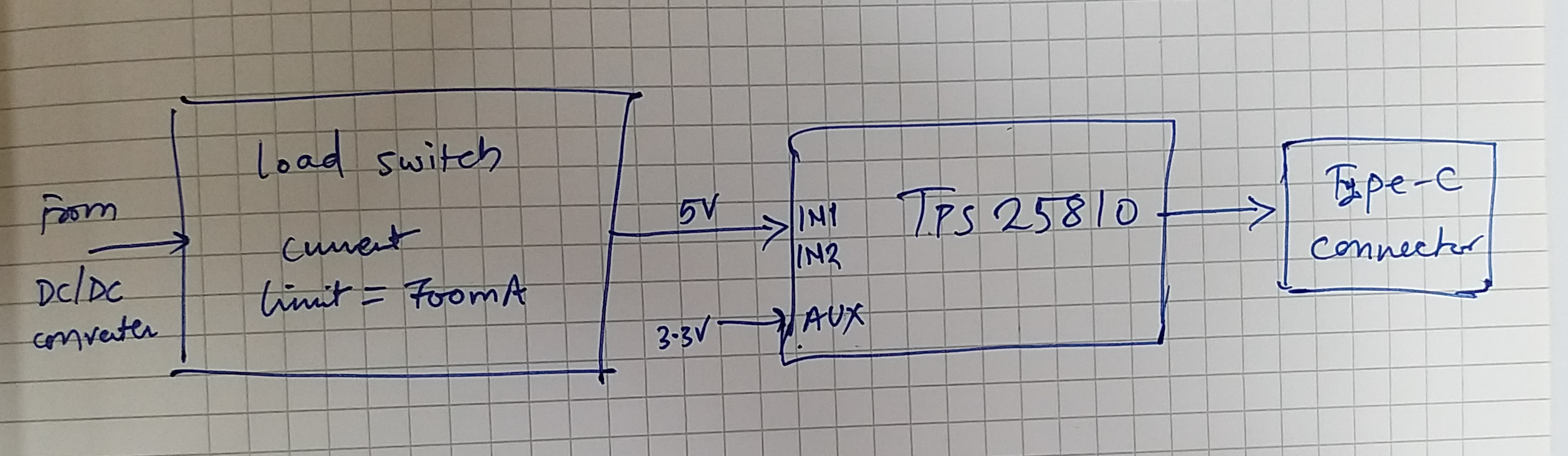
TPS25810 has an internal short circuit current limit of 1.7A. I have a circuit where I want to limit the current to 700mA. I am planning to use the following scheme.

My question is: What is the behavior of TPS25810 DFP controller, when its input voltage starts dropping in over current event and then comes back again?

Does it have any effect on the communication?

Is it a good idea to have load switch between TPS25810 & Type-C connector instead of the below scheme?

Regards,

Sanjay R. Pithadia

  • Hi Sanjay,

    With your load switch, the TPS25810 should never go into over current. During an over current event, the TPS25810 will assert FAULT. The TPS25810 will use an internal current-limit regulator to limit the output current to the current limit and the output voltage is determined by ios (short circuit current limit) x RLOAD. There are two scenarios with an overload condition:

    • The input voltage is first applied, enable is true, and a short circuit is present (IOUT > ios)
      • The output voltage is held near zero potential with respect to ground and the TPS25810 ramps the output current to ios. The TPS25810 limits the current to ios until the overload condition is removed or the device begins to thermal cycle.
    • The device is enabled and fully turned on and an overload occurs
      • The device response varies between simply settling to ios or turnoff and controlled return to ios, depending on the overload level, input circuit, and rate of application. The TPS25810 limits the current to ios until the overload condition is removed or the device begins to thermal cycle. 

    The device will thermal cycle if an overload condition is present long enough to activate thermal limiting. The details of thermal shutdown are described in the datasheet:

    You should place the load switch between the DC/DC converter and the TPS25810, as you have done in your drawing.

    Thanks,

    Emma