This thread has been locked.

If you have a related question, please click the "Ask a related question" button in the top right corner. The newly created question will be automatically linked to this question.

DS90UB954-Q1: Configuration with DS90UB913

Part Number: DS90UB954-Q1


Dear experts,

I have a system the looks like the following block diagram:

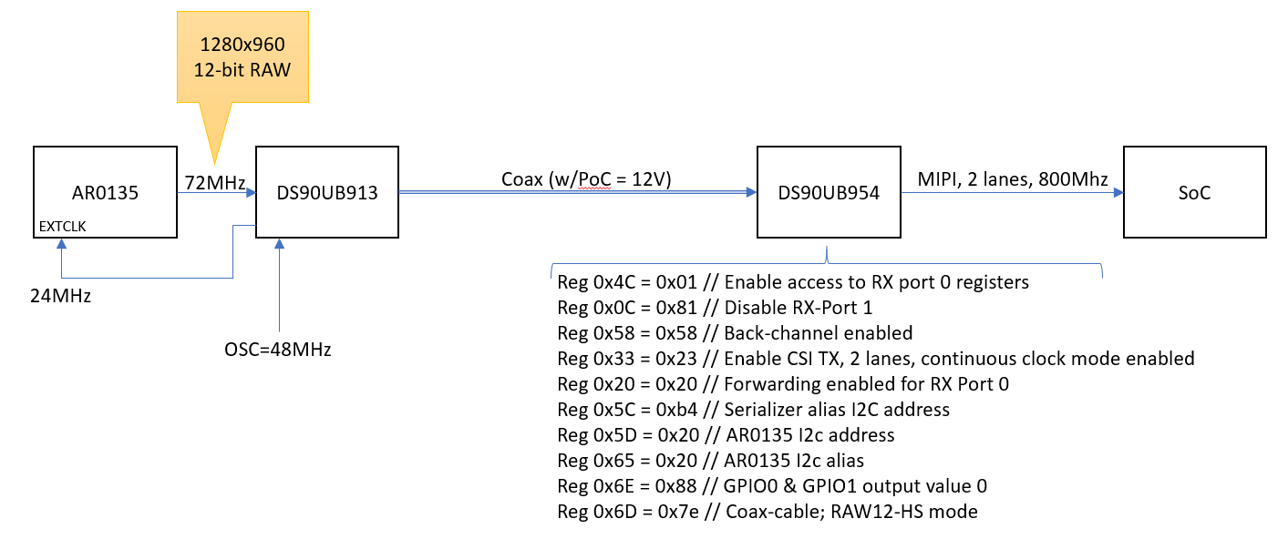
The problem is that I'm not getting any data at the SoC and no error indication. It seems no data is being transmitted from the 954.

I do see the LINE_COUNT and LINE_LEN registers update, so the deserializer is getting data from the 913. But it's not getting to the SoC.

However, if I connect a different camera module (AR0144 + 953), the system works.

Also, if I place the 954 in PGEN mode, it works.

I am stuck in figuring out why the system doesn't work.  Can you provide guidelines how to resolve the issue?

Regards,

Erez


  • Hello Erez,

    Most likely the issue the MODE selection for 954. When paired with 953 you must used CSI-2 mode, but when paired with 913A you must use RAW mode. Please try strapping the MODE pin into MODE 2 from table 2 in the datasheet or use register 0x6D[1:0] to set RAW12 Mode/75 MHz. 

    Best Regards,

    Casey 

  • Hello Casey,

    I already have that setting enabled via register 0x6d.

    However, I found out that the order of register initialization makes a difference. 

    Seems registers 0x6d needs to be written before register 0x33.

    Now it is working...

    Erez