


Part Number: DP83822IF
Hi all
Would you mind if we ask DP83822IF?
<Question1>
In relaion to following forum, we have the question of pull up or pull down at LED_1 pin in case of boot strap setting.
e2e.ti.com/.../2775945
We recognize that LED_1 needs pull resistance to configure MODE1 and MODE4.
"It is a strap pin, but the pin is for internal use only. This is why the pin must be strapped to either MODE1 or MODE4. MODE2 and MODE3 are not allowed."
In oreder to configure MODE1 and MODE4, we would like to confirm resitance setting in case of using LED.
LED_1 pin has internal pull down. So, on following DP83822 EVM circuit,
J11 1-2 short : Mode4
J11 2-3 short : Mode1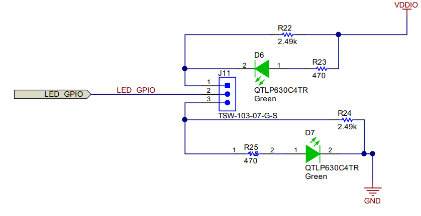
Is our recognition correct?
<Question2>
Our customer would like to use LED_1 with Link status.
We guess that it is possible to configure it using LEDCFG1 register(0x0460 LEDs Configuration Register).
Is our recognition correct?
<Question3>
On "Table 13. LED Configuration", there is the description "LED_1 tri-state".
In case of CRS Strap Mode1 and Mode 4, LED_1 is tri-state.
In relation to <Question2>, after start-up with LED_1 tri-state, is it possible to configure LED_1 with Link status using LEDCFG1 register?
And then, does it require to change B2-0 of IOCTRL1(0x0462 IO MUX GPIO Control Register) from 000(Tri-State) to 001(LED)?
Kind regards,
Hirotaka Matsumoto
