This thread has been locked.

If you have a related question, please click the "Ask a related question" button in the top right corner. The newly created question will be automatically linked to this question.

SN65HVD234: Standby connection

Part Number: SN65HVD234

Hi

I want to have CAN network of 64 nodes with minimum possible overall current consumption using SN65HVD234.

The idea is to keep all devices in standby and enable one driver only. My problem is how to enable driver.

Bus speed is 50kbps, with bit time 20us. Driver goes from standby to dominant within max. 1,5us, seems enough.

How fast goes back to standby?

Here's what I tested till now:

1. Usually there's no 'RX byte' interrupt in controller, only after RX whole frame, but it's too late for driving ACK to the bus.

2. I don't want to enable all transceivers from beginning of each frame, because I need to do it in all nodes and overall current consumption increases too much.

3. I didn't found CAN controllers with dedicated standby pin, do they exist? So the idea is to control Rs pin from TX of controller like this (modified example from DS):

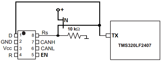
When TX is low, D is dominant, N FET is disabled and Rs is connected to 10k to ground (slope control).

When TX goes high, S is recessive, N pulls Rs high and transceiver goes standby.

Is my understanding correct?

  • Hello,

    This an is an unusual way to use the device, so we need to spend a little time thinking through it to see whether there are potential issues. We will get back to you within the next few days.

    Regards,

    Max

  • Hi Bogumil,

    As Max stated, this is an unusual way to use this device. This setup would essentially be using Rs as the D pin (but inverted) to drive a dominant when enabled and allow a decay to recessive when disabled. As the timing for standby to dominant is defined as you pointed out, this would likely work for a dominant transition. When transitioning to recessive, as long as the D pin is driven early enough for the driver state to settle before the device switches to standby mode, this would likely fit the timing for a slow 50kbps bit-rate. In short, there is no apparent flaw using the device in this way. However, because it is an abnormal use and there may be unexpected behaviors due to uncharacteristically fast switching on Rs, I would like to propose another solution.

    Because TMS320LF2407 does not have a dedicated standby output, I would recommend using a GPIO pin to control SN65HVD234's Rs pin through the slope-control resistor. This way the controller will have direct control of the device state independent of the transmitting data and the node can remain in standby if the received message does not pertain to it. In order to interrupt the node before the end of the message frame, SN65HVD234's R pin can be connected to another GPIO of TMS320LF2407 that is configured as an interrupt. This way, when R transitions due to CAN traffic, the controller can wake with enough time to process the message and ACK if necessary. This interrupt can be disabled after the initial transition and re-enabled when returning to standby. 

    Depending on your system, unused SCI pins or SPI pins would likely be easiest to configure as the standby contorl pins as they are on the same event manager as the CAN pins. One of the external interrupt pins can be used as the R pin interrupt for incoming messages. 

    Let me know if this suggestion seems reasonable or if you would like to further explore the idea displayed in your figure. If there are other requirements for your system that you can share it may make it easier to recommend an alternative solution.

    Regards,
    Eric

  • Dear Eric

    Thank You for detailed explanation.

    We don't use now TMS320, it was just one from datasheet example. Do You know if microcontrollers with dedicated standby pin exist?

    I'm not sure if I understand Your idea correctly - in additional GPIO interrupt routine, after each received bit, I should check CAN controller

    state/status, if received frame is correct/completed and enable transceiver for ACK? I'm not sure, if this is possible, but I'll try for sure.

    Meanwhile, I started testing my solution (100m cables, 5 nodes, room temperature) and it works on desk. I needed only to replace one N-FET with P-FET,

    to be fully enabled from 3V3 rail, + second P-FET for signal inverting.

    Measured standby to dominant time, back to standby time, propagation delay of tranceiver + 100m cable - all together are about 2-3us, seems OK for 20us bit.

  • Hi Bogumil,

    Eric is out of the office at the moment, but to respond to your question I'm not aware of MCUs that would have a dedicated "STB" output pin to go to a CAN transceiver.  It is common to assign one of an MCU's GPIO pins to do this function, though.  You could use this to keep the transceiver in standby mode until it needs to transmit a frame or acknowledge a received frame.

    That said, you have come up with a pretty creative approach - thanks for sharing it and letting us know your progress.  I'd be interested to hear the outcome of the future tests you have planned.

    Regards,
    Max