Part Number: TCA9517A
Hello,
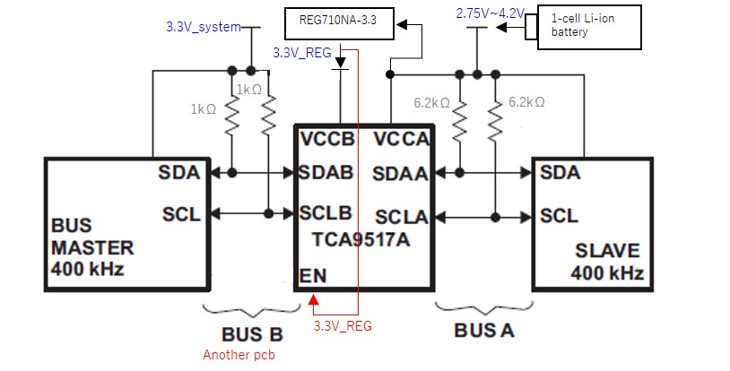
I am considering using the TCA9517A with the following configuration. Is there a problem with my usage?
Also, In my circuit, is VOL less than 0.6V under any condition?
(About variations such as differences between LOTs, individual differences, temperature..)
Please comment if you have any concerns.
Best Regards,
Truenalia