Tool/software: TI C/C++ Compiler
hi:
we use dp83822i in one project ,we config the 83822 as RMII mode connect with tm4c1292ncpdt,Using slave mode。
the PHY works fine, but the MAC doesn't receive data, and it doesn't receive interrupts
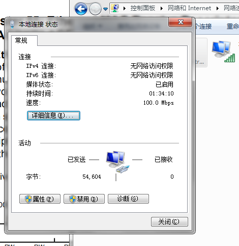
phy 100m link up
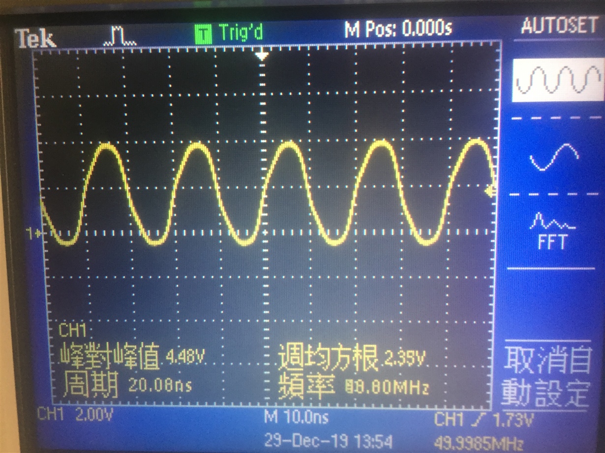
clock:
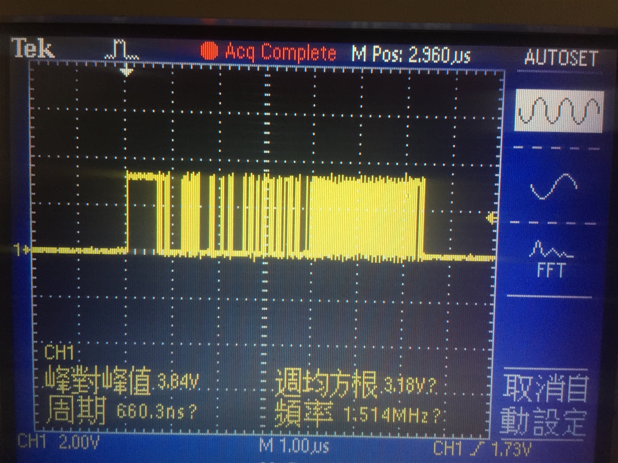
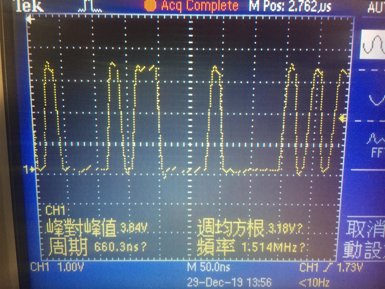
phy rx_d0:
Partial register value:
PHY_BMCR: 0x00003100
PHY_BMSR: 0x00007849
PHY_ID1: 0x00002000
PHY_ANA: 0x000001e1
PHY_ANLPA: 0x00000000
PHY_ANER: 0x00000004
PHY_CR1: 0x00000000
PHY_PHYCR: 0x00008021
PHY_CFG2: 0x00000100
PHY_FLDS: 0x00000000
PHY_PHYSTS: 0x00004002
PHY_RCSR: 0x000000e1
PHY_10BTSCR: 0x00000000
PHY_COMPT: 0x00002001
PHY_FLDS: 0x00000000
PHY_CR2: 0x00000100
PHY_LDCTRL: 0x00009fcf
PHY_EEECFG2: 0x00000302
PHY_MLEDCR: 0x0000002b
PHY_IOCTRL1: 0x00000001
PHY_LEDCFG1: 0x00000851
PHY_PHYSTS: 0x00000715
PHY_PHYSCR: 0x0000010b
MAC_EMACCC: 0x00010000
MAC_EMACPC: 0xc0000000
MAC_EMACPP: 0x00000100
phy to mcu
tx_en
tx_d0
tx_d1
rx_dv
rx_d0
rx_d1
mdc
mdio
clock:
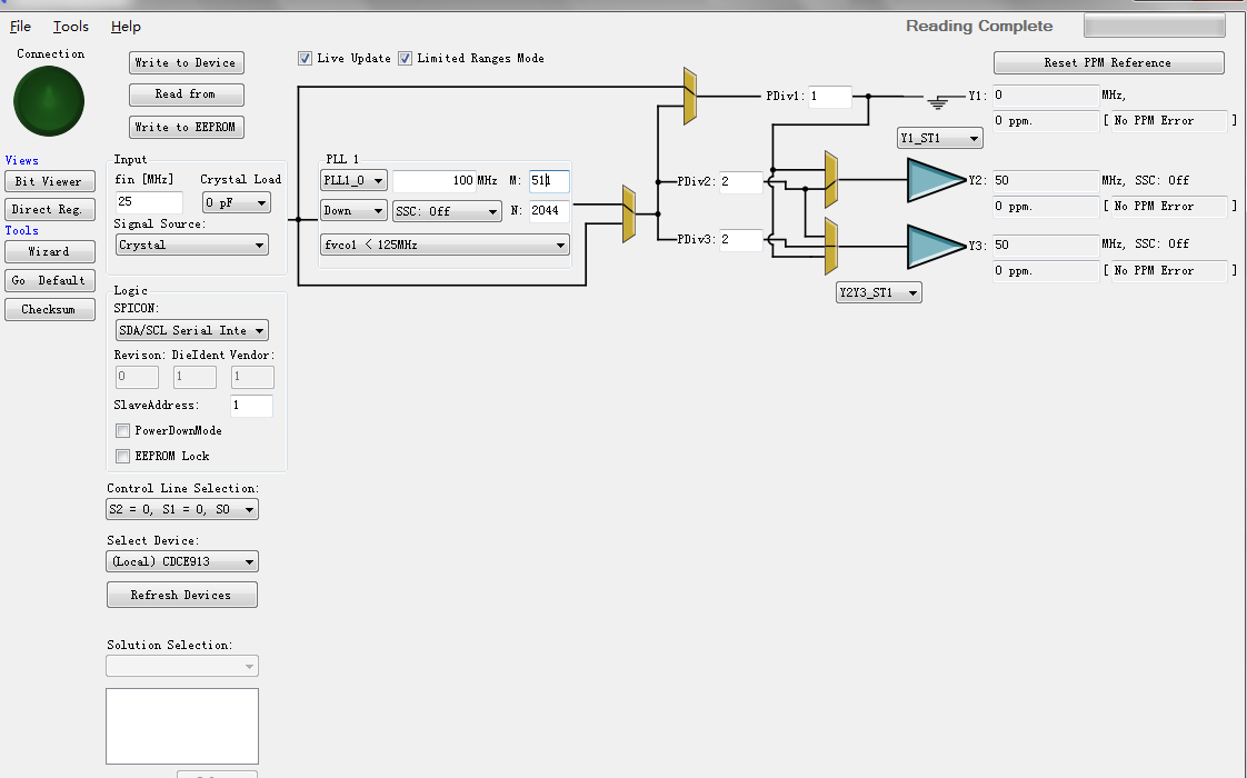
50Mhz
Crystal ----- CDCE913PW ---------------- LMK00804BQWRGTTQ1 -------- phy xi
-------- mcu ref_clk
mcu init code:
uint8_t pui8MACArray[8] = {0xAC, 0xDE, 0x48, 0x00, 0x80, 0x00};
ROM_SysCtlPeripheralEnable(SYSCTL_PERIPH_GPIOA);
ROM_SysCtlPeripheralEnable(SYSCTL_PERIPH_GPIOB);
ROM_SysCtlPeripheralEnable(SYSCTL_PERIPH_GPIOC);
ROM_SysCtlPeripheralEnable(SYSCTL_PERIPH_GPIOD);
ROM_SysCtlPeripheralEnable(SYSCTL_PERIPH_GPIOE);
ROM_SysCtlPeripheralEnable(SYSCTL_PERIPH_GPIOF);
ROM_SysCtlPeripheralEnable(SYSCTL_PERIPH_GPIOG);
ROM_SysCtlPeripheralEnable(SYSCTL_PERIPH_GPIOH);
ROM_SysCtlPeripheralEnable(SYSCTL_PERIPH_GPIOJ);
ROM_SysCtlPeripheralEnable(SYSCTL_PERIPH_GPIOK);
ROM_SysCtlPeripheralEnable(SYSCTL_PERIPH_GPIOL);
ROM_SysCtlPeripheralEnable(SYSCTL_PERIPH_GPIOM);
ROM_SysCtlPeripheralEnable(SYSCTL_PERIPH_GPION);
ROM_SysCtlPeripheralEnable(SYSCTL_PERIPH_GPIOP);
ROM_SysCtlPeripheralEnable(SYSCTL_PERIPH_GPIOQ);
ROM_GPIOPinConfigure(GPIO_PG7_EN0RXDV);
ROM_GPIOPinConfigure(GPIO_PQ5_EN0RXD0);
ROM_GPIOPinConfigure(GPIO_PQ6_EN0RXD1);
ROM_GPIOPinConfigure(GPIO_PG3_EN0TXEN);
ROM_GPIOPinConfigure(GPIO_PG4_EN0TXD0);
ROM_GPIOPinConfigure(GPIO_PG5_EN0TXD1);
ROM_GPIOPinConfigure(GPIO_PF2_EN0MDC);
ROM_GPIOPinConfigure(GPIO_PF3_EN0MDIO);
ROM_GPIOPinConfigure(GPIO_PK4_EN0INTRN);
ROM_GPIOPinConfigure(GPIO_PM4_EN0RREF_CLK);
GPIODirModeSet(GPIO_PORTG_BASE, GPIO_PIN_5 | GPIO_PIN_6 | GPIO_PIN_7, GPIO_DIR_MODE_HW);
GPIODirModeSet(GPIO_PORTQ_BASE, GPIO_PIN_4 | GPIO_PIN_5 | GPIO_PIN_3, GPIO_DIR_MODE_HW);
GPIODirModeSet(GPIO_PORTF_BASE, GPIO_PIN_2 | GPIO_PIN_3, GPIO_DIR_MODE_HW);
GPIODirModeSet(GPIO_PORTK_BASE, GPIO_PIN_4, GPIO_DIR_MODE_HW);
GPIODirModeSet(GPIO_PORTM_BASE, GPIO_PIN_4, GPIO_DIR_MODE_HW);
GPIOPadConfigSet(GPIO_PORTG_BASE, GPIO_PIN_5 | GPIO_PIN_6 | GPIO_PIN_7, GPIO_STRENGTH_8MA, GPIO_PIN_TYPE_STD);
GPIOPadConfigSet(GPIO_PORTQ_BASE, GPIO_PIN_4 | GPIO_PIN_5 | GPIO_PIN_3, GPIO_STRENGTH_8MA, GPIO_PIN_TYPE_STD);
GPIOPadConfigSet(GPIO_PORTF_BASE, GPIO_PIN_2 | GPIO_PIN_3, GPIO_STRENGTH_8MA, GPIO_PIN_TYPE_STD);
GPIOPadConfigSet(GPIO_PORTK_BASE, GPIO_PIN_4, GPIO_STRENGTH_8MA, GPIO_PIN_TYPE_STD);
GPIOPadConfigSet(GPIO_PORTM_BASE, GPIO_PIN_4, GPIO_STRENGTH_8MA, GPIO_PIN_TYPE_STD);
ROM_SysCtlPeripheralEnable(SYSCTL_PERIPH_EMAC0);
ROM_SysCtlPeripheralEnable(SYSCTL_PERIPH_EMAC0);
while(!ROM_SysCtlPeripheralReady(SYSCTL_PERIPH_EMAC0))
{
}
EMACPHYConfigSet(EMAC0_BASE, EMAC_PHY_TYPE_EXTERNAL_RMII);
while(!SysCtlPeripheralReady(SYSCTL_PERIPH_EMAC0))
{
}
ROM_EMACReset(EMAC0_BASE);
while(!SysCtlPeripheralReady(SYSCTL_PERIPH_EMAC0))
{
}
EMACInit(EMAC0_BASE, 120000000, EMAC_BCONFIG_TX_PRIORITY | EMAC_BCONFIG_MIXED_BURST |
EMAC_BCONFIG_DMA_PRIO_WEIGHT_2 | EMAC_BCONFIG_PRIORITY_2_1, 8, 8, 0);
ROM_EMACConfigSet(EMAC0_BASE,
(EMAC_CONFIG_FULL_DUPLEX | EMAC_CONFIG_CHECKSUM_OFFLOAD |
EMAC_CONFIG_7BYTE_PREAMBLE | EMAC_CONFIG_IF_GAP_96BITS |
EMAC_CONFIG_USE_MACADDR0 |
EMAC_CONFIG_SA_FROM_DESCRIPTOR |
EMAC_CONFIG_BO_LIMIT_1024),
(EMAC_MODE_RX_STORE_FORWARD |
EMAC_MODE_TX_STORE_FORWARD |
EMAC_MODE_TX_THRESHOLD_64_BYTES |
EMAC_MODE_RX_THRESHOLD_64_BYTES), 0);
InitDescriptors(EMAC0_BASE);
ROM_EMACAddrSet(EMAC0_BASE, 0, (uint8_t *)&pui8MACArray);
while((ROM_EMACPHYRead(EMAC0_BASE, EPHY_ADDAR, EPHY_BMSR) & EPHY_BMSR_LINKSTAT) == 0)
{
}
ROM_EMACFrameFilterSet(EMAC0_BASE, (EMAC_FRMFILTER_SADDR |
EMAC_FRMFILTER_PASS_MULTICAST |
EMAC_FRMFILTER_PASS_NO_CTRL));
ROM_EMACIntClear(EMAC0_BASE, EMACIntStatus(EMAC0_BASE, false));
ROM_EMACTxEnable(EMAC0_BASE);
ROM_EMACRxEnable(EMAC0_BASE);
ROM_IntEnable(INT_EMAC0);
ROM_EMACIntEnable(EMAC0_BASE, EMAC_INT_RECEIVE);
ROM_EMACIntEnable(EMAC0_BASE, EMAC_INT_PHY);
g_psRxDescriptor[g_ui32RxDescIndex].ui32CtrlStatus |= DES0_RX_CTRL_OWN;
//
// LED_0 Config
//
// 0101 = Speed, High for 100Base-TX
EMACPHYExtendedWrite(EMAC0_BASE, EPHY_ADDR, EPHY_LEDCFG, 0x2B);
//
// LED_1 config
//
// 1000 = LINK OK / BLINK on TX/RX Activity
EMACPHYExtendedWrite(EMAC0_BASE, EPHY_ADDR, EPHY_IOCTRL1, 0x1);
//-------------------------------------------------------------------
// Initialize the transmit and receive DMA descriptors.
//-------------------------------------------------------------------
void InitDescriptors(uint32_t ui32Base)
{
uint32_t ui32Loop;
//
// Initialize each of the transmit descriptors. Note that we leave the OWN
// bit clear here since we have not set up any transmissions yet.
//
for(ui32Loop = 0; ui32Loop < NUM_TX_DESCRIPTORS; ui32Loop++)
{
g_psTxDescriptor[ui32Loop].ui32Count =
(DES1_TX_CTRL_SADDR_INSERT |
(TX_BUFFER_SIZE << DES1_TX_CTRL_BUFF1_SIZE_S));
g_psTxDescriptor[ui32Loop].pvBuffer1 = g_pui8TxBuffer;
g_psTxDescriptor[ui32Loop].DES3.pLink =
(ui32Loop == (NUM_TX_DESCRIPTORS - 1)) ?
g_psTxDescriptor : &g_psTxDescriptor[ui32Loop + 1];
g_psTxDescriptor[ui32Loop].ui32CtrlStatus =
(DES0_TX_CTRL_LAST_SEG | DES0_TX_CTRL_FIRST_SEG |
DES0_TX_CTRL_INTERRUPT | DES0_TX_CTRL_CHAINED |
DES0_TX_CTRL_IP_ALL_CKHSUMS);
}
//
// Initialize each of the receive descriptors. We clear the OWN bit here
// to make sure that the receiver doesn't start writing anything
// immediately.
//
for(ui32Loop = 0; ui32Loop < NUM_RX_DESCRIPTORS; ui32Loop++)
{
g_psRxDescriptor[ui32Loop].ui32CtrlStatus = 0;
g_psRxDescriptor[ui32Loop].ui32Count =
(DES1_RX_CTRL_CHAINED |
(RX_BUFFER_SIZE << DES1_RX_CTRL_BUFF1_SIZE_S));
g_psRxDescriptor[ui32Loop].pvBuffer1 = g_pui8RxBuffer;
g_psRxDescriptor[ui32Loop].DES3.pLink =
(ui32Loop == (NUM_RX_DESCRIPTORS - 1)) ?
g_psRxDescriptor : &g_psRxDescriptor[ui32Loop + 1];
}
//
// Set the descriptor pointers in the hardware.
//
ROM_EMACRxDMADescriptorListSet(ui32Base, g_psRxDescriptor);
ROM_EMACTxDMADescriptorListSet(ui32Base, g_psTxDescriptor);
//
// Start from the beginning of both descriptor chains. We actually set
// the transmit descriptor index to the last descriptor in the chain
// since it will be incremented before use and this means the first
// transmission we perform will use the correct descriptor.
//
g_ui32RxDescIndex = 0;
g_ui32TxDescIndex = NUM_TX_DESCRIPTORS - 1;
}
startup_rvmdk.S
;******************************************************************************
;
; <o> Stack Size (in Bytes) <0x0-0xFFFFFFFF:8>
;
;******************************************************************************
Stack EQU 0x00000800
;******************************************************************************
;
; <o> Heap Size (in Bytes) <0x0-0xFFFFFFFF:8>
;
;******************************************************************************
Heap EQU 0x00000000
;******************************************************************************
;
; Allocate space for the stack.
;
;******************************************************************************
AREA STACK, NOINIT, READWRITE, ALIGN=3
StackMem
SPACE Stack
__initial_sp
;******************************************************************************
;
; Allocate space for the heap.
;
;******************************************************************************
AREA HEAP, NOINIT, READWRITE, ALIGN=3
__heap_base
HeapMem
SPACE Heap
__heap_limit
;******************************************************************************
;
; Indicate that the code in this file preserves 8-byte alignment of the stack.
;
;******************************************************************************
PRESERVE8
;******************************************************************************
;
; Place code into the reset code section.
;
;******************************************************************************
AREA RESET, CODE, READONLY
THUMB
;******************************************************************************
;
; External declarations for the interrupt handlers used by the application.
;
;******************************************************************************
EXTERN EthernetIntHandler
;******************************************************************************
;
; The vector table.
;
;******************************************************************************
EXPORT __Vectors
__Vectors
DCD StackMem + Stack ; Top of Stack
DCD Reset_Handler ; Reset Handler
DCD NmiSR ; NMI Handler
DCD FaultISR ; Hard Fault Handler
DCD IntDefaultHandler ; The MPU fault handler
DCD IntDefaultHandler ; The bus fault handler
DCD IntDefaultHandler ; The usage fault handler
DCD 0 ; Reserved
DCD 0 ; Reserved
DCD 0 ; Reserved
DCD 0 ; Reserved
DCD IntDefaultHandler ; SVCall handler
DCD IntDefaultHandler ; Debug monitor handler
DCD 0 ; Reserved
DCD IntDefaultHandler ; The PendSV handler
DCD IntDefaultHandler ; The SysTick handler
DCD IntDefaultHandler ; GPIO Port A
DCD IntDefaultHandler ; GPIO Port B
DCD IntDefaultHandler ; GPIO Port C
DCD IntDefaultHandler ; GPIO Port D
DCD IntDefaultHandler ; GPIO Port E
DCD IntDefaultHandler ; UART0 Rx and Tx
DCD IntDefaultHandler ; UART1 Rx and Tx
DCD IntDefaultHandler ; SSI0 Rx and Tx
DCD IntDefaultHandler ; I2C0 Master and Slave
DCD IntDefaultHandler ; PWM Fault
DCD IntDefaultHandler ; PWM Generator 0
DCD IntDefaultHandler ; PWM Generator 1
DCD IntDefaultHandler ; PWM Generator 2
DCD IntDefaultHandler ; Quadrature Encoder 0
DCD IntDefaultHandler ; ADC Sequence 0
DCD IntDefaultHandler ; ADC Sequence 1
DCD IntDefaultHandler ; ADC Sequence 2
DCD IntDefaultHandler ; ADC Sequence 3
DCD IntDefaultHandler ; Watchdog timer
DCD IntDefaultHandler ; Timer 0 subtimer A
DCD IntDefaultHandler ; Timer 0 subtimer B
DCD IntDefaultHandler ; Timer 1 subtimer A
DCD IntDefaultHandler ; Timer 1 subtimer B
DCD IntDefaultHandler ; Timer 2 subtimer A
DCD IntDefaultHandler ; Timer 2 subtimer B
DCD IntDefaultHandler ; Analog Comparator 0
DCD IntDefaultHandler ; Analog Comparator 1
DCD IntDefaultHandler ; Analog Comparator 2
DCD IntDefaultHandler ; System Control (PLL, OSC, BO)
DCD IntDefaultHandler ; FLASH Control
DCD IntDefaultHandler ; GPIO Port F
DCD IntDefaultHandler ; GPIO Port G
DCD IntDefaultHandler ; GPIO Port H
DCD IntDefaultHandler ; UART2 Rx and Tx
DCD IntDefaultHandler ; SSI1 Rx and Tx
DCD IntDefaultHandler ; Timer 3 subtimer A
DCD IntDefaultHandler ; Timer 3 subtimer B
DCD IntDefaultHandler ; I2C1 Master and Slave
DCD IntDefaultHandler ; CAN0
DCD IntDefaultHandler ; CAN1
DCD EthernetIntHandler ; Ethernet
DCD IntDefaultHandler ; Hibernate
DCD IntDefaultHandler ; USB0
DCD IntDefaultHandler ; PWM Generator 3
DCD IntDefaultHandler ; uDMA Software Transfer
DCD IntDefaultHandler ; uDMA Error
DCD IntDefaultHandler ; ADC1 Sequence 0
DCD IntDefaultHandler ; ADC1 Sequence 1
DCD IntDefaultHandler ; ADC1 Sequence 2
DCD IntDefaultHandler ; ADC1 Sequence 3
DCD IntDefaultHandler ; External Bus Interface 0
DCD IntDefaultHandler ; GPIO Port J
DCD IntDefaultHandler ; GPIO Port K
DCD IntDefaultHandler ; GPIO Port L
DCD IntDefaultHandler ; SSI2 Rx and Tx
DCD IntDefaultHandler ; SSI3 Rx and Tx
DCD IntDefaultHandler ; UART3 Rx and Tx
DCD IntDefaultHandler ; UART4 Rx and Tx
DCD IntDefaultHandler ; UART5 Rx and Tx
DCD IntDefaultHandler ; UART6 Rx and Tx
DCD IntDefaultHandler ; UART7 Rx and Tx
DCD IntDefaultHandler ; I2C2 Master and Slave
DCD IntDefaultHandler ; I2C3 Master and Slave
DCD IntDefaultHandler ; Timer 4 subtimer A
DCD IntDefaultHandler ; Timer 4 subtimer B
DCD IntDefaultHandler ; Timer 5 subtimer A
DCD IntDefaultHandler ; Timer 5 subtimer B
DCD IntDefaultHandler ; FPU
DCD 0 ; Reserved
DCD 0 ; Reserved
DCD IntDefaultHandler ; I2C4 Master and Slave
DCD IntDefaultHandler ; I2C5 Master and Slave
DCD IntDefaultHandler ; GPIO Port M
DCD IntDefaultHandler ; GPIO Port N
DCD 0 ; Reserved
DCD IntDefaultHandler ; Tamper
DCD IntDefaultHandler ; GPIO Port P (Summary or P0)
DCD IntDefaultHandler ; GPIO Port P1
DCD IntDefaultHandler ; GPIO Port P2
DCD IntDefaultHandler ; GPIO Port P3
DCD IntDefaultHandler ; GPIO Port P4
DCD IntDefaultHandler ; GPIO Port P5
DCD IntDefaultHandler ; GPIO Port P6
DCD IntDefaultHandler ; GPIO Port P7
DCD IntDefaultHandler ; GPIO Port Q (Summary or Q0)
DCD IntDefaultHandler ; GPIO Port Q1
DCD IntDefaultHandler ; GPIO Port Q2
DCD IntDefaultHandler ; GPIO Port Q3
DCD IntDefaultHandler ; GPIO Port Q4
DCD IntDefaultHandler ; GPIO Port Q5
DCD IntDefaultHandler ; GPIO Port Q6
DCD IntDefaultHandler ; GPIO Port Q7
DCD 0 ; Reserved
DCD 0 ; Reserved
DCD 0 ; Reserved
DCD 0 ; Reserved
DCD 0 ; Reserved
DCD 0 ; Reserved
DCD IntDefaultHandler ; Timer 6 subtimer A
DCD IntDefaultHandler ; Timer 6 subtimer B
DCD IntDefaultHandler ; Timer 7 subtimer A
DCD IntDefaultHandler ; Timer 7 subtimer B
DCD IntDefaultHandler ; I2C6 Master and Slave
DCD IntDefaultHandler ; I2C7 Master and Slave
DCD 0 ; Reserved
DCD 0 ; Reserved
DCD 0 ; Reserved
DCD 0 ; Reserved
DCD 0 ; Reserved
DCD IntDefaultHandler ; I2C8 Master and Slave
DCD IntDefaultHandler ; I2C9 Master and Slave
DCD 0 ; Reserved
DCD 0 ; Reserved
DCD 0 ; Reserved
;******************************************************************************
;
; This is the code that gets called when the processor first starts execution
; following a reset event.
;
;******************************************************************************
EXPORT Reset_Handler
Reset_Handler
;
; Enable the floating-point unit. This must be done here to handle the
; case where main() uses floating-point and the function prologue saves
; floating-point registers (which will fault if floating-point is not
; enabled). Any configuration of the floating-point unit using
; DriverLib APIs must be done here prior to the floating-point unit
; being enabled.
;
; Note that this does not use DriverLib since it might not be included
; in this project.
;
MOVW R0, #0xED88
MOVT R0, #0xE000
LDR R1, [R0]
ORR R1, #0x00F00000
STR R1, [R0]
;
; Call the C library enty point that handles startup. This will copy
; the .data section initializers from flash to SRAM and zero fill the
; .bss section.
;
IMPORT __main
B __main
;******************************************************************************
;
; This is the code that gets called when the processor receives a NMI. This
; simply enters an infinite loop, preserving the system state for examination
; by a debugger.
;
;******************************************************************************
NmiSR
B NmiSR
;******************************************************************************
;
; This is the code that gets called when the processor receives a fault
; interrupt. This simply enters an infinite loop, preserving the system state
; for examination by a debugger.
;
;******************************************************************************
FaultISR
B FaultISR
;******************************************************************************
;
; This is the code that gets called when the processor receives an unexpected
; interrupt. This simply enters an infinite loop, preserving the system state
; for examination by a debugger.
;
;******************************************************************************
IntDefaultHandler
B IntDefaultHandler
;******************************************************************************
;
; Make sure the end of this section is aligned.
;
;******************************************************************************
ALIGN
;******************************************************************************
;
; Some code in the normal code section for initializing the heap and stack.
;
;******************************************************************************
AREA |.text|, CODE, READONLY
;******************************************************************************
;
; The function expected of the C library startup code for defining the stack
; and heap memory locations. For the C library version of the startup code,
; provide this function so that the C library initialization code can find out
; the location of the stack and heap.
;
;******************************************************************************
IF :DEF: __MICROLIB
EXPORT __initial_sp
EXPORT __heap_base
EXPORT __heap_limit
ELSE
IMPORT __use_two_region_memory
EXPORT __user_initial_stackheap
__user_initial_stackheap
LDR R0, =HeapMem
LDR R1, =(StackMem + Stack)
LDR R2, =(HeapMem + Heap)
LDR R3, =StackMem
BX LR
ENDIF
;******************************************************************************
;
; Make sure the end of this section is aligned.
;
;******************************************************************************
ALIGN
;******************************************************************************
;
; Tell the assembler that we're done.
;
;******************************************************************************
END
//
// // There's no interruption here
//
void EthernetIntHandler(void)
{
uint32_t ui32Status;
ui32Status = MAP_EMACIntStatus(EMAC0_BASE, true);
MAP_EMACIntClear(EMAC0_BASE, ui32Status);
UARTprintf("INT: %08x \r\n", ui32Status);
}
hope get answer quickly .
thank you very much


