This thread has been locked.

If you have a related question, please click the "Ask a related question" button in the top right corner. The newly created question will be automatically linked to this question.

DP83867IR: Pinging issue with gigabit switch

Part Number: DP83867IR
Other Parts Discussed in Thread: DP83867ERGZ-R-EVM

Hello,

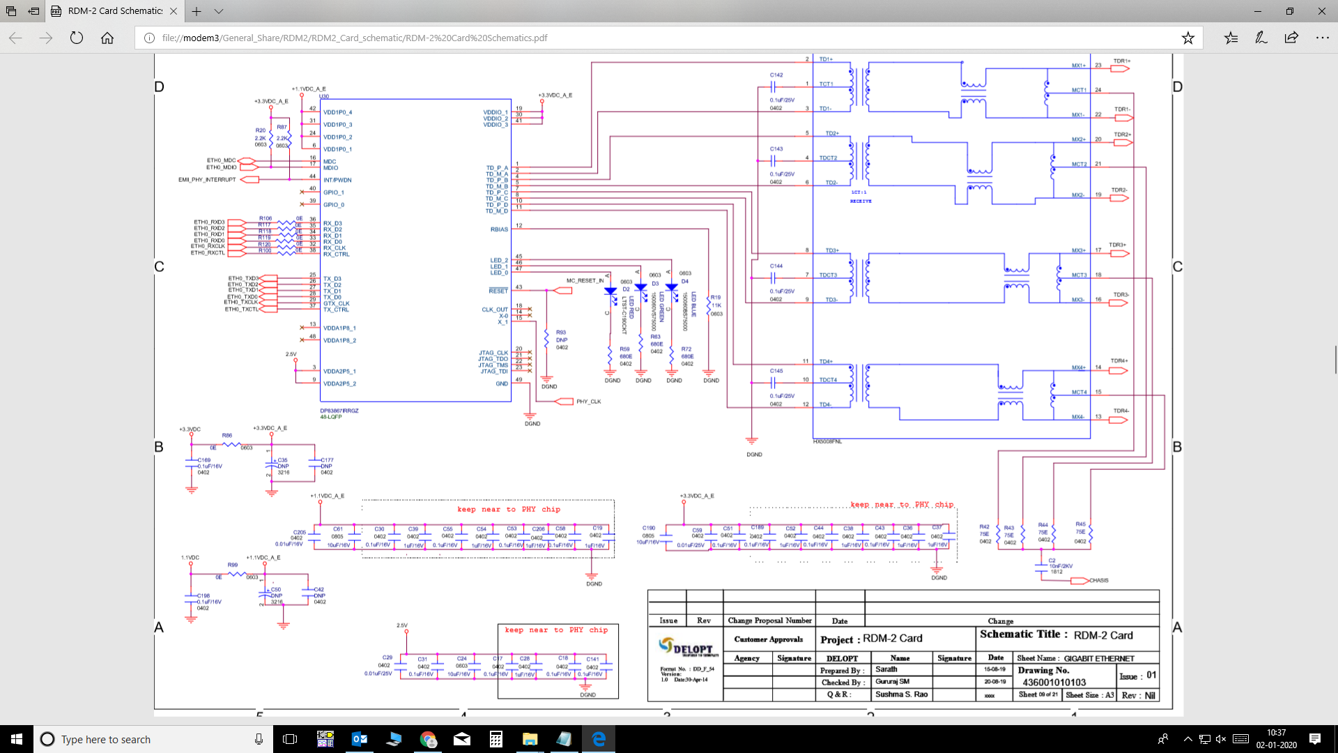
We are using gigabit phy Ethernet in RGMII mode it was working fine in my PC (LINUX RHEL 7.3 OS) but when i connect the gigabit switch between my card and PC  i cannot able ping the card and by debugging i came know that it had struck in the interrupt and it was not coming out from that until switch is Disconnected is there related to hardware or software by the way we have followed the same from DP83867 EVM schematics  please help me to come out from the issue

Regards

Sarath M

  • Hello Sarath,

    1. Can you please confirm what your hardware bootstraps are set to and if there was any additional registers configured through MDIO / MDC?
    2. Are you using the 48-pin or 64-pin part / EVM? DP83867IRPAP-EVM or DP83867ERGZ-R-EVM?
    3. Can you please send me the read values of MICR (register address 0x0012) and ISR (register address 0x0013) so I can understand what interrupt has been triggered?
    4. "by debugging i came know that it had struck in the interrupt" What were your debug steps?

    Thanks,

    Vibhu

  • Hello Vibhu 

    we don't have any strap configurations because we using power on reset all the configuration are done through MDIO and MDC you can find the register data below 

    you can find Phy register data with switch and with system when i ping.

    --With Switch dp83867_reg---------
    MODECTL - 0x1000
    MODESTAT - 0x796d
    PHYID1 - 0x2000
    PHYID2 - 0xa231
    ANAR - 0x5e1
    ANLPAR - 0xcde1
    ANER - 0x6d
    1KTCR - 0x300
    STS1 - 0x3800
    PHYCR - 0x5048
    PHYSTS - 0xac02
    MICR - 0x6c00
    ISR - 0x0
    IO_MUX_CFG - 0x5048
    RGMIICTL - 0x6c00
    TIME - 0x6d
    -----------------------------

    --With System dp83867_reg--------

    MODECTL - 0x1000
    MODESTAT - 0x796d
    PHYID1 - 0x2000
    PHYID2 - 0xa231
    ANAR - 0x5e1
    ANLPAR - 0xcde1
    ANER - 0x6d
    1KTCR - 0x300
    STS1 - 0x7c00
    PHYCR - 0x5048
    PHYSTS - 0xac02
    MICR - 0x6c00
    ISR - 0x0
    IO_MUX_CFG - 0x5048
    RGMIICTL - 0x6c00
    TIME - 0x6d

    We are using DP83867IRRGZ 48 pin LQFP Package for custom design below is the schematics.

    We have 25Mhz oscillator with 3.3V source and having 27pF capacitor divider (C1&C2) as suggested in datasheet, not shown in above schematics sheet.

    i am using ADSP- SC587 processor, when  i connect to switch i kept a break point over the PHY interrupt. When connected to system Ethernet port it is coming out from the interrupt and pinging, and with switch it  struck at PHY interrupt and it is not coming out until disconnect from switch Ethernet port.

    Probed the data pins and clock pins  in PHY, found the difference with switch and with system is below:

    1)Probed RXD0 when it is connected to system a bunch of data will come to some time and it will be high all the time and RX_CLK is 125 MHZ

    2)Probed RXD0 when it is connected to switch right after connecting to the switch i can see 125 MHZ clock at the RXD0 i don't understand which factors are causing this problem when it is connected to switch.

    Please do needful... 

    Regards

    Sarath M

  • Hello 

    Waiting for your reply if you have solution please let us know ASAP

    Regards

    Sarath M

  • Hello Sarath,

    Based on the difference in your register reads:

    Switch: STS1 - 0x3800 vs System: STS1 - 0x7c00

    It looks like in the switch case bit 10 indicates that "Link partner not capable of 1000Base-T Half Duplex" however register 0x0000 bit [8] indicates the PHY is set to "Half Duplex Operation".

    In the original post you say "working fine in my PC (LINUX RHEL 7.3 OS) but when i connect the gigabit switch between my card and PC  i cannot able ping the card". My understanding is with the system or PC it works fine, but with the switch, the gigabit switch in between it doesn't, please confirm this. So the first set of registers is when you can't transfer information? The second set of registers is good?

    Thanks,

    Vibhu

  • Hello Vibhu,

    we have solved that issue by understanding  same kind of scenario in one of the forms regarding gigabit switch. So thing is when ever we connect to switch my PHY(DP83867IRRGZ ) is becoming slave and the gigabit switch is acting as master so we hard coded in such way to  that the phy will always master. That's fine is there any other method without hard coding and one of my Analog devices evaluation(ADSP-SC589EVM) board is working fine with switch and PC without  any hard coding can it  be possible to not to hard code it??

    Thanks and regards

    Sarath M

  • Hello Sarath,

    When in auto-negotiation "The Master mode priority is given to the device that supports multiport nodes, such as switches and repeaters. Single node devices such as DTE or NIC card takes lower Master mode priority." this is in "8.4.3.2 Master and Slave Resolution" section of the datasheet.

    You will have to program the part to set to master.

    Are you using register 0x0009 for this?

    Thanks,

    Vibhu

  • Hello Sarath,

    Do you have an update on this, please let me know.

    Thanks,

    Vibhu

  • Hello Vibhu ,

     i have used same  register  and now it working fine with switch and with PC. thank you

    Regards

    sarath