This thread has been locked.

If you have a related question, please click the "Ask a related question" button in the top right corner. The newly created question will be automatically linked to this question.

TCA9535: PCA9555 IO Configuration issue in Output Mode

Part Number: TCA9535

Hello,

We are using TCA9535 in our design. We have configured all IO's as output and I have made PO7, PO1 as HIGH by using I2C command. 

1st I2C command :

1st Byte: Address

2nd Byte: 0x02

3rd Byte: 0x41

4th Byte: 0x00

Now I want to make P02 as HIGH by Keeping previous IO states same. 

2nd I2C command :

1st Byte: Address

2nd Byte: 0x02

3rd Byte: 0x61

4th Byte: 0x00

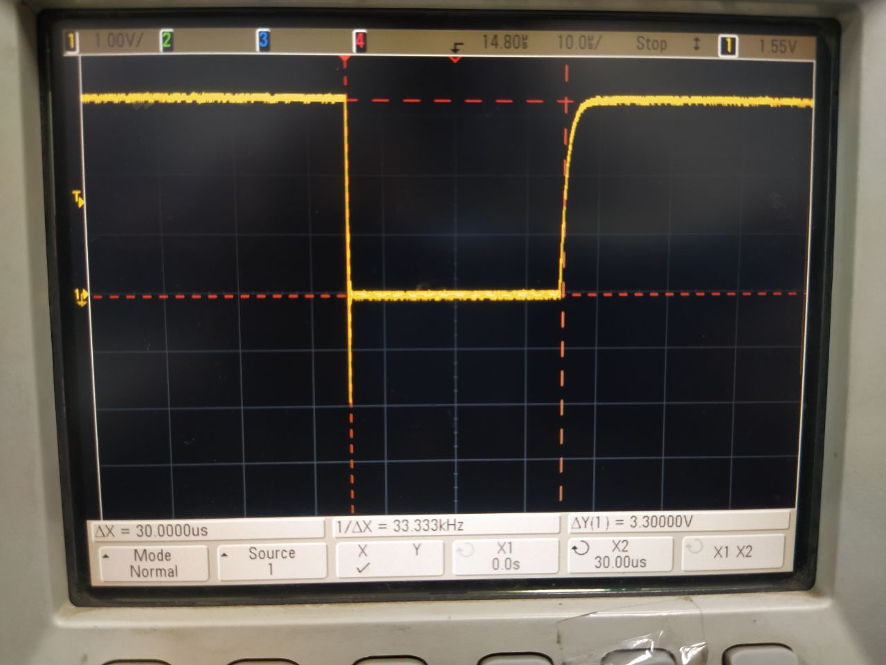
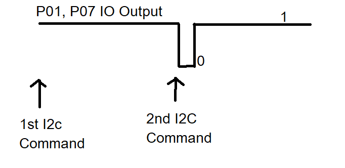
After writing the 2nd I2C command, I am seeing that P01, P07 IO's will go low and then go to High.

Is it Expected behavior? [ Refer Below diagram] 

If YES, Please let me know any other part which will not be doing this behavior. We need IO Expander In WHICH io output should not be changed until I2C data changes. 

if NO, Please let us know how to resolve this?

Thanks in advance,

best Regards

Harshavardhan Reddy. 

  • Hi, Harshavardhan

    Thank you for the detailed explanation and figure.

    A low pulse from the I/O Pin is not expected when overwriting a HIGH bit with another HIGH bit. The output logic for this device is flip-flop based and will only drive values that are passed in from the shift register during a write pulse.

    Please provide some information to help diagnose possible causes:
    Would you be able to share scope shots of the I2C lines during these commands? What is the width of the pulse on the output pins? Are there any other transactions (other reads or writes) that cause the outputs to pulse in this way? Is there any other transactions occuring to th IO expander before these bits are re-written? What kind of load is being driven by the output pin?

    Regards,
    Eric

  • Hi Eric,

    Thanks for responding. Please find my comments below. 

    Would you be able to share scope shots of the I2C lines during these commands?

    [Harsha] Please find attached Image

    What is the width of the pulse on the output pins?

    [Harsha] Width of the pulse is close to 30uSec

    Are there any other transactions (other reads or writes) that cause the outputs to pulse in this way?

    [Harsha] No other transactions are done while doing this. 

    Is there any other transactions occurring to th IO expander before these bits are re-written?

    [Harsha] No transactions. I have verified in scope. 

    What kind of load is being driven by the output pin?

    [Harsha] It is not driving any load. It connected to Test pin which is connected to scope. 


    Regards,

    Harshavardhan.

  • Hi Harshavardhan,

    Thank you for the timing information. Could you provide a bit more information?

    Would you be able to share the section of code in question? Also, could you include SDA and SCL in the scope shots with P07/P01? It would be helpful to see the transaction that causes this behavior and where it occurs with respect to the I2C data.

    Regards,
    Eric

  • Hi Eric,

    We are seeing I2C transactions are perfect. We are suspecting something problem is with our code. Can you please help with this?

    Our Application, we need to make both Ports are Output ports and Change IO state of outputs to 1 or 0 based on the requirement.

    Sample COde : 

    I2C start

    1St Byte : Slave address

    2nd Byte : 0x06

    3rd Byte and 4th byte: 0xFF 0xFF 

    I2C Stop

    I2C Start

    1st Byte: slave address

    2nd Byte: 0x02

    3rd Byte and 4th Byte: x00 0xFF    [ Port0 all IO 's are LOW, Port1 All IO's HIHG]

    I2C Stop

  • Hi Gonugunta,

    It appears in the sample code you shared, you are configuring all IO Ports as inputs (addresses 0x06, 0x07 set to 0xFF). "If a bit in [the configuration] register is set to 1, the corresponding port pin is enabled as an input with a high-impedance output driver. If a bit in this register is cleared to 0, the corresponding port pin is enabled as an output." If the device is configured in this way, changing the values in the output registers (0x02, 0x03) will have no effect on the pins. "Bit values in [the output] register have no effect on pins defined as inputs." Could you confirm that the waveform you shared occurs when the device ports are configured as outputs?

    I am interested to see when the pulse occurs in relation to the I2C communication. It would be helpful to see SDA, SCL, and P01/P07 when the pulse occurs to get relative timing of the event. I would also like to check that the data on SDA, SCL matches what we should expect based on the pseudo-code you are sharing. 

    Regards,

    Eric

  • Hi Gonugunta,

    Are you still experiencing the I/O pulse when writing to TCA9535's output register? If you were able to find a solution, we would like to document it here if possible. 

    Regards,
    Eric