This thread has been locked.

If you have a related question, please click the "Ask a related question" button in the top right corner. The newly created question will be automatically linked to this question.

AM26C32: Pull-up resistor value

Part Number: AM26C32


Hi


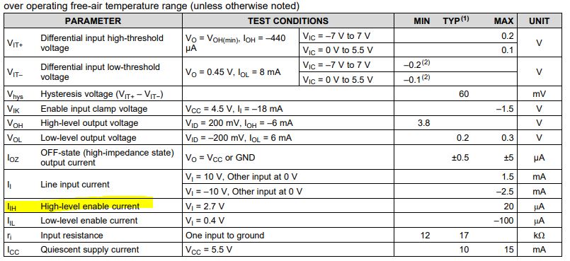
Are there any recommended value for pull-up resister ?

Is it ok if it could drive the high-level enable current ?


Thank you and best regards,

Michiaki

  • Hi Michiaki-san,

    The High-level enable current is a consumption specification. This is the maximum current that will leak through the input under the specified conditions. Pull-up resistors for the enable input should allow this much current while still providing a valid HIGH voltage at the pin. For example, pulling up to Vcc = 5V - the voltage drop across the pull-up resistor should not exceed Vcc - Vil (5V - 2V = 3V). If the maximum current drawn from this pin is 20uA, our theoretical Max pull-up resistor value is (3V / 20uA) 150k=ohm. 

    The minimum value would be defined by what is driving the enable line and weather it can pull LOW stronger than the pull-up resistor pulls HIGH. This would be roughly Rpu > (Vcc – Vilinput) / Ioldriver. Other considerations would be timing requirements of the enable and how the RC timing will impact pull-up enable times. Strong pull-ups (smaller R values) also provide increased noise immunity.

    We typically recommend pull-up resistors within the 1k to 10k-ohm range to improve noise current reduction. Depending on the requirements of your system (enable driver, consumption needs, noise level, etc.) a value in this range or closer to 100k-ohm will serve the needs of AM26C32.

    Let me know if you have any more questions.

    Regards,

    Eric


  • Hi Eric,


    Let me make sure the receiver output state when input is in the absence of a valid input signal.

    AM26C32 output is high in the case of the above ?


    Our customer tested in the above case and see the phenomenon output become low state.


    Datasheet describes “The AM26C32 has an internal circuit that ensures functionality during an idle bus” so customer think AM26C32 could output high when inputs is in the absence of a valid input signal.


    Thank you and best regards,

    Michiaki

  • Hi Michiaki-san,

    Let me make sure the receiver output state when input is in the absence of a valid input signal.

    AM26C32 output is high in the case of the above?

    Yes, internal failsafe circuitry attempts to put the receiver output in a known (High) state during a open or idle bus condition.

    Our customer tested in the above case and see the phenomenon output become low state.

    The failsafe circuitry is designed to bias the receiver when the bus is in an open or near 0V differential state. When the input is somewhere in the indeterminate range and not near 0V, the output is not defined (may be High or Low). Noise coupled on the bus may also cause the undefined output to change. A common method to avoid these problems is to implement an external fail-safe biasing circuit to put the bus in a valid High state when open or idle. Check out these application notes for more information on how to implement an external failsafe bias network:

    http://www.ti.com/lit/an/slyt324/slyt324.pdf

    http://www.ti.com/lit/an/slyt514/slyt514.pdf

    Let me know if this makes sense.

    Regards,

    Eric

  • Hi Eric,

    Let me make sure how to fix the output state for the below case.


    -        To fix output state to low.

    -        To fix output stage to high

    • Put external fail-safe biasing circuit.
      In the case, are there any recommendation value for resister of biasing circuit ?


    Thank you and best regards,

    Michiaki

  • Hi Michiaki,

    Your understanding is correct. In the case where the output state is fixed LOW, it is essentially failsafe biasing to the opposite state (bus LOW instead of bus HIGH). The 1k to 10k-ohms that Max suggested is a common range of failsafe resistor values (Rfs). To calculate theoretical values to use for your system, I would recommend looking at the description of Figure 2 (page 2) of the RS-485: Passive failsafe for an idle bus article. It outlines the calculations for an example system that are likely similar to your application. 

    Let me know if you have any questions about this.

    Regards,

    Eric