This thread has been locked.

If you have a related question, please click the "Ask a related question" button in the top right corner. The newly created question will be automatically linked to this question.

How to configure the des/ser for a hub?


Hi,

I have a requeirement of using hub to connect the DS954 with the sensor, how to configure the registers?

The handware connection is : ds954a->hub(ds953a->ds954b)->sensor(ds913a->ov10635 or ds953b->cmos).

I tried, and only get the first three devices 954a+953a+954b, the most is 954a+953a+954b+953b. For sensor ov10635, I even can't get ds913. For the other sensor, I can get ds953b, but can't get access to the cmos.

Then what registers should be configured and how for 954a+953a+954b+913a or 954a+953a+954b+953b?

  • Hello Xn,

    Can you please post a block diagram for the system you are trying to build? It is hard to understand from the explanation. 

    Best Regards,

    Casey 

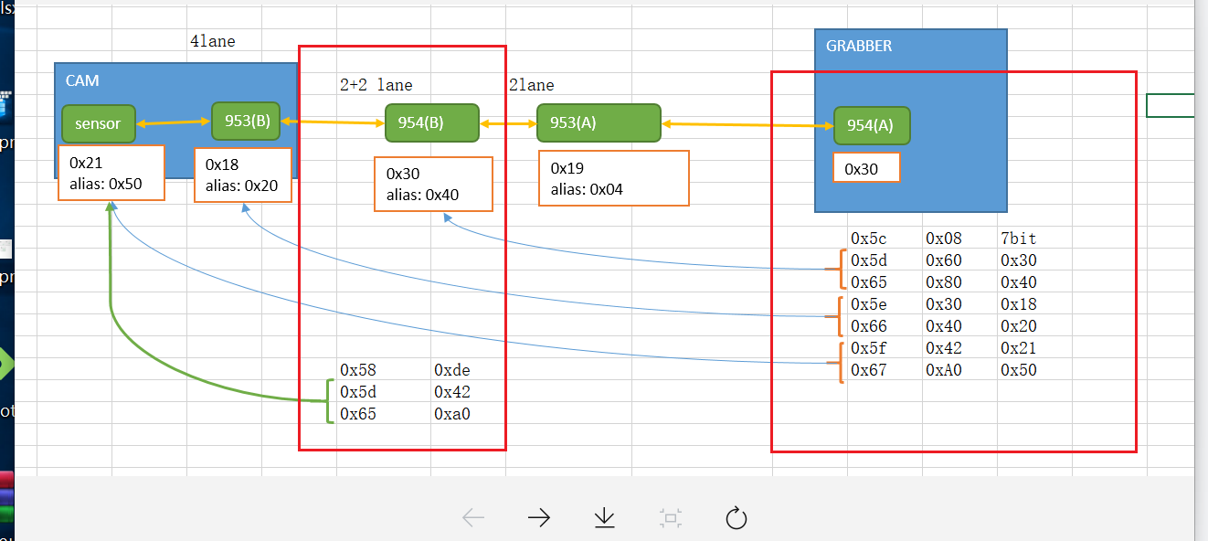
  • Hi, as the picture shows. 

    For ds954a, the other registers' configuration is :

    0x4c: 0x01

    0x58: 0x5e

    0x6d: 0x7c

    For ds953a, the registers' configuration is :

    i2cset -y -f 0 0x2d 0x01 0x03
    sleep 0.1
    i2cset -y -f 0 0x2d 0x02 0x53
    sleep 0.1
    i2cset -y -f 0 0x2d 0x0e 0x30

    For ds954b, the registers' configuration is :

    i2cset -y -f 0 0x3c 0x1f 0x03
    i2cset -y -f 0 0x3c 0x33 0x61
    i2cset -y -f 0 0x3c 0x20 0x30
    sleep 0.1
    i2cset -y -f 0 0x3c 0x4c 0x01
    i2cset -y -f 0 0x3c 0x58 0xde
    i2cset -y -f 0 0x3c 0x5c 0x20 
    i2cset -y -f 0 0x3c 0x5d 0x42
    i2cset -y -f 0 0x3c 0x65 0xa0 
    i2cset -y -f 0 0x3c 0x7c 0x81
    i2cset -y -f 0 0x3c 0x70 0x1e
    i2cset -y -f 0 0x3c 0x6d 0x7c

    For ds953b, the registers' configuration is :

    i2cset -f -y 0 0x2c 0x01 0x03
    i2cset -f -y 0 0x2c 0x02 0x33

    If I connect the sensor directly with grabber with the configration of ds954a, I can get access to the 953b and sensor.

    Then if I want to get access to the sensor with the picture show, what should I do?

  • Hi xn,

    Here's an example of how to communicate to multiple slaves:

    Also if you are connecting a 954 to a 913A serializer, then you'll need to follow the below steps to set it for backwards compatibility mode:

    • On 954:
    • Check Mode Pin to make sure it's in RAW mode
    • Check register 0x58 to make sure it's using 2.5Mbps back channel freq
    • Check the AC coupling caps, with 913A, use 100nF for Rin+ and 47nF for Rin- in coax mode
    • Check the PoC network for make sure it follows the 2G network
    • Verify FV and LV signal timing

    Best,

    Jiashow

  • Hi,

    Thanks for replying. Anyway, it still doesn't work.

    My configuration is:

    #954a
    i2cset -y -f 0 0x3d 0x01 0x03
    sleep 1
    i2cset -y -f 0 0x3d 0x4c 0x01
    i2cset -y -f 0 0x3d 0x21 0x81
    i2cset -y -f 0 0x3d 0x33 0x21
    i2cset -y -f 0 0x3d 0x20 0x20
    i2cset -y -f 0 0x3d 0x42 0x71
    i2cset -y -f 0 0x3d 0x5c 0x30 //for 953a
    i2cset -y -f 0 0x3d 0x5d 0x60 //954b real addr
    i2cset -y -f 0 0x3d 0x65 0x80 //954b alias addr
    i2cset -y -f 0 0x3d 0x5e 0x36 //953b alias addr as you shows
    i2cset -y -f 0 0x3d 0x66 0x36 //953b alias addr as you shows
    i2cset -y -f 0 0x3d 0x5f 0x34  //sensor alias addr as you shows
    i2cset -y -f 0 0x3d 0x67 0x34 //sensor alias addr as you shows
    i2cset -y -f 0 0x3d 0x58 0xde //pass through && pass through all && 953
    i2cset -y -f 0 0x3d 0x6d 0x44
    i2cset -y -f 0 0x3d 0xd5 0xf0

    #954b
    i2cset -y -f 0 0x30 0x01 0x03
    sleep 1
    i2cset -y -f 0 0x30 0x4c 0x01
    i2cset -y -f 0 0x30 0x21 0x81
    i2cset -y -f 0 0x30 0x33 0x21
    i2cset -y -f 0 0x30 0x20 0x20
    i2cset -y -f 0 0x30 0x42 0x71
    i2cset -y -f 0 0x30 0x5c 0x36 //953b alias addr
    i2cset -y -f 0 0x30 0x5d 0x20 //sensor real addr
    i2cset -y -f 0 0x30 0x65 0x34 //sensor alias addr
    i2cset -y -f 0 0x30 0x58 0xde //pass through && pass through all && 953
    i2cset -y -f 0 0x30 0x6d 0x44
    i2cset -y -f 0 0x30 0xd5 0xf0

    I also tried to change the value of 0x58 to 0x5e, still didn't work.

    Could you please tell me why I should set the  slave id of 0x5e && 0x5f to alias addr, but not real addr?

    And where is wrong for my configuration that makes the system not work?

  • Hi xn,

    For 954A, you need to set the aliases for the sensor and 953B for the real address because these devices are not physically connected as a 954A slave (they are slaves for the 954B). We want the 954A to simply propagate the I2C address to the 954B, and have the 954B to remap the alias to the real address.

    Definitely set 0x58 = 0x5E. Which device(s) are you not able to communicate to? Can you make sure the address you are communicating to is correct in terms of 7-bit or 8-bit?

    The diagram you provided has the addresses in 7-bit right? How come 954A says I2C address 0x30 and you are talking to 0x3D in the code?

    Also try setting 953a alias to an address other than 0x30.

    Best,

    Jiashow