This thread has been locked.

If you have a related question, please click the "Ask a related question" button in the top right corner. The newly created question will be automatically linked to this question.

TPS65987D: TPS65987D Patch Update Error -- ROM Incompatible

Part Number: TPS65987D
Other Parts Discussed in Thread: TPS65987, TIDA-050012

Hello,

I'm attempting to update a TPS65987D over I2C following the PTCx command sequence.
I successfully transfer all the data in chunks of 64 bytes, but upon sending the PTCc command, in Byte 3 of the response, DevicePatchCompleteStatus I receive a 0x42 (Patch not compatible with this version of ROM).


My device is a TPS65987DDHRSHR, and the utility I used to get a patch file was version 6.1.1, using the TPS65987_88_F707_10_08.bin
This same patch successfully loads to the EVM from the utility and runs correctly. 

I have tried multiple new, and stock patch files with the same 0x42 result.

Attached is a link to my i2c capture of the whole patch update. (External link due to file upload extension rules):
https://drive.google.com/open?id=10JelenN30IFiRcX4KKddaJjvHSRX_6JE
This capture covers going from:

  1. PTCr
  2. PTCs
  3. PTCd (Iterated for whole Patch)
  4. PTCc (Has the 0x42 error)

The file can be opened using Total Phase Data Center. The error is annotated at the bottom. 


This seems to be the same issue as http://e2e.ti.com/support/interface/f/138/t/842397?TPS65987D-TPS65987D which had no resolution. 

Any help would be appreciated,
Jeff

  • Hi Jeff,

    Would you be able to check the top side marking of the device you have populated on your system? I'm interested in the lettering on the second line. The EVM and your board should both match in saying "DH". Would like to double check this with you.

  • Adam,

    Yes, both my EVM and board have the "DH" lettering. 

  • Jeff,

    Let me check this item with my team. In parallel, would you be able to elaborate on why you or your customer wants to use the functionality of the PTCx commands instead of the external ROM?

  • Adam,

    There is no external FLASH dedicated to the USB-PD chip in the design.

    Please let me know the response from the team,
    Jeff

  • Any further developments on this?

    I'm still stuck with the same patching error which is rendering the USB-PD chip useless.

    Thanks,
    Jeff

  • Hi Jeff,

    No I have not had a chance to test this myself yet. Would you be able to share the project file you are using as well as the binary image you are programming onto the device?

  • Adam,

    The ROM error don't seem to change based on 3 different projects/configs I tried.
    Attached is the main project intended for the product.

    --Jeff

    KP4B.pjtKP4B.c

  • Hey Jeff,

    We have a system using an MDP430 launchpad and our PD controller EVM to replicate an EC I2C update. However, I am having difficulties getting that up and running at the moment so I may have to work through you until I can get that setup going again.

    Since you are using the EC update over I2C I recommend you use the advanced project template as opposed to the standard. Here are some steps to try and get this working on your system

    1. Create a new project using the advanced template, copying over your preferences from the previous project file

    2. Once you have the new project, click on Settings -> Show Bitfield Ranges (will show each individual bit position in respects to that register)

    3. Pinstrap the ADCINx pins to where it starts into BP_NoWait

    4. In the configuration tool, open Interrupt Mask for I2C1 (register 0x16) and enable bits 80 and 81

    5. Refer to Figure 2 in the following document http://www.ti.com/lit/an/slva972a/slva972a.pdf focusing on the first box. Within your EC code, have the EC see the IRQ event, read what event cause the IRQ event, and if it was the Ready_for_Patch interrupt, follow through with the PTC commands and the rest of the flow chart

    6. Generate the new binary image from the configuration tool by clicking Binary -> Save Binary -> Low Region .c

    These steps cover a few things that I think could be causing you troubles. Let me know if you have any questions.

  • Adam,

    Just by your suggestion of enabling the INT for the 2 bits, ReadyForPatch & PatchLoaded, the PTCx process is now returning success from PTCc and I can negotiate higher voltages.

    However, I would like some clarification on running this patch update from dead-battery mode as I'm running into some weirdness there. I have 2 cases using the same Patch file:

    1. Board is powered exclusively by USB, in dead-battery mode. I run through PTCx update successfully, send "DBfg" and it stays at 5V even though DBfg returns success in the CMD register. (DBfg instead of Gaid in dead battery mode as per: https://e2e.ti.com/support/interface/f/138/t/801218?TPS65987D-Please-let-me-know-how-to-re-patch found by Gaid causing system reset.)
    2. Board is externally powered in addition to USB power. I run through PTCx update successfully, and send "Gaid", 20V comes up. I can then remove the external power, and 20V powers the whole system.

    We intend to use the device as per use case 1, but I can't yet negotiate the higher voltage without the Gaid and external power. 

    Think I am very close here thanks to your help,

    Jeff

  • Hey Jeff,

    Glad to hear that you were able to get the patch update working successfully.

    One thing you can try is have the EC write the 'GSrC' 4cc command which would have the PD controller request the source capabilities from the connected charger. This should start the power negotiation sequence again and the PD controller should then request the 20V contract based on its updated sink capabilities.

    One thing I would recommend though is to not clear the dead battery flag unless you have a battery or some internal power supply providing power to the PD controller.

  • Adam, 

    Thanks for the input.

    I removed the 'DBfg' as per your suggestion, and tried 'GSrC' following the PTCx update. The 20V still is not negotiated during the dead battery mode.

    I also attempted a 'SWSk' with no success.

    Anything else I can try?

    Thanks,
    Jeff

  • Hi Jeff,

    What is the dead battery mode and device configuration you have your system set to (ADCIN1 and 2 values).

  • Adam,

    ADCIN1 is biased to Configuration 3 with BP_NoWait. 
    ADCIN2 is grounded.

    --Jeff

  • Instead of configuration 3, could you use the 'Safe' configuration to see if that works? You will still negotiate a 5V contract when the device is in dead battery mode, but will be done using an internal pull down resistor as opposed to a PD contract.

  • Adam,

    I can't bias to the 'Safe' configuration as the SPI MISO is grounded. Unfortunately, both the trace and via to ground is underneath the part.

    --Jeff

  • Okay, last suggestion then I think the Gaid is the only option. Are you sure that you are in configuration 3? By default, the PD controller should negotiate a 20V contract if the source is capable of supplying it (refer to table 7 in datasheet). Do you have a PD analyzer available? If so, read the sink capabilities sent by your system as it boots from a dead battery condition. It should advertise sink capabilities up to 20V so you should see that in the PD communication

  • Adam,

    Unfortunately I do not have access to a PD analyzer.

    As far as I know I am in Configuration 3 with BP_NoWait, but I have never been able to negotiate >5 as specified in the datasheet from dead-battery mode.
    I had some back and forth with Hari Patel on the subject, but did not come to a resolution which led me down this PTCx update path.

    If I can get the dead battery mode to work this will also solve my problem, so maybe you have some input there.

    My measured ADCIN1 voltage is 1.45V which should put me at DIV 0.44 [R1 = 150K, R2 = 120K, referenced to LDO_3V3] with SPI MISO grounded.

    Is there a way to verify config through registers? Is there any other things I should check?

    Thanks for the continued support,
    Jeff

  • Hi Adam,

    Just poking again, I still have not been able to negotiate any higher voltage through dead battery / USB-only power.
    If this isn't possible/part of a chip errata I will need to look to issue a recall and spin a new board with a new USB PD chip.

    Thanks,
    Jeff

  • Hi Jeff,

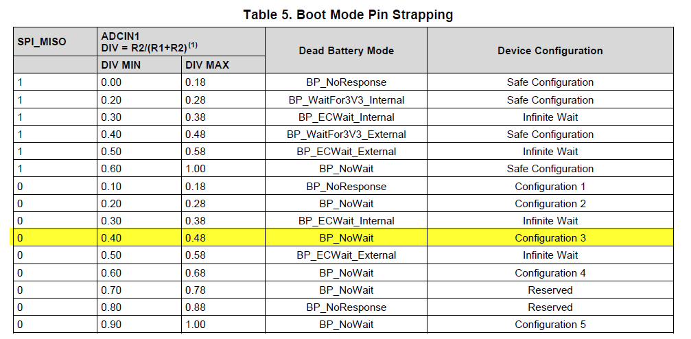
    I just tested the default configuration highlighted below using an EVM, which is the one I believe you are using. I was able to successfully negotiate a 20V contract using the default config and a Type-C PD charger. Recommend that you check to make sure you are in the correct configuration (resistor pin strapping). This is an example of when a PD analyzer would be useful to see what capabilities the charger is advertising and what the PD controller is accepting/negotiating

  • Hi Adam,

    Thanks for testing this out, this is different than my results. I have 2 questions for your setup:

    1. Is a Patch file being loaded into the EVM by ANY method for your test? (FLASH/I2C/SPI)
    2. Is the board being powered by any other source than the USB-PD port?

    This is the exact configuration I would like to use, but my own experimentation and multiple other users forum posts have the result of only being able to negotiate 5V from resistor pin strapping of ADCIN1.

    Thanks,
    Jeff

  • Hey Jeff,

    Answers to your questions.

    1. No I am only using the default configuration highlighted above

    2. No it is booting from a dead battery condition (powered from VBUS and not VIN_3V3)

    My test setup used the TPS65987EVM and the TIDA-050012 as the dedicated source supplying the 20V to the EVM. Was able to successfully enter into a 20V contract following this setup using the default configuration.

    One thing you can do to ensure you are loading the proper default configuration is to read the register defining the sink capabilities of the PD controller and determine whether or not it is the 20V that it should be. This is an important step to ensure the PD controller is advertising the correct sink capabilities and is in the correct configuration since you do not have a PD analyzer

  • Adam, 

    I appreciate the tests you have run for me!

    Can you verify that when you are running your experiment on the TPS65987EVM:

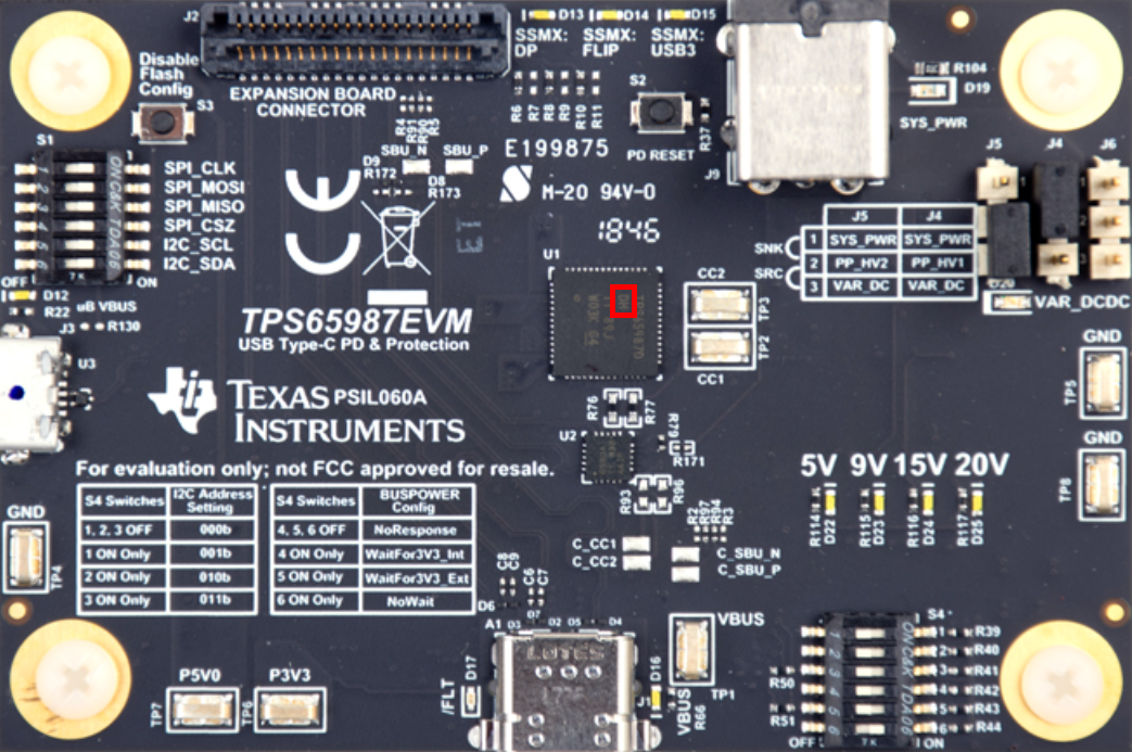
    1. You are pressing S3 to disable Flash Config while you plug in the USB power (Grounds SPI_MISO)
    2. S4 switch 6 is the only switch on. (BP_NoWait)

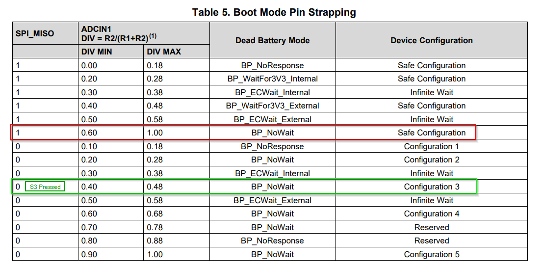
    I think you are booting into Safe Mode (Red Box), and loading a patch via SPI to get the higher voltage negotiated. The green boxed configuration is my boards setup.

    I ran through the experiment and can negotiate the higher voltage when S3 is not-pressed and device configuration is in Safe mode. I can see SPI activity during the boot process when this happens, so I assume a patch or configuration is being loaded into the chip that allows the higher voltage. 

    However, I only ever get 5V when I hold S3 and go into Configuration 3 during boot, although it should be able to negotiate 5-20V dictated by the Configuration 3 description. With the S3 button pressed there is no SPI activity. This fundamental issue that started the whole I2C patch discussion.

    Please let me know if you get the same results with S3 pressed, as this is accurate for my SPI-less board.

    Thanks for sticking with me through these frustrations,
    Jeff

  • Hey Jeff,

    Of course, happy to help!

    As far as the SPI flash, it is fully disabled as I switched off the SPI CLK and MOSI line so that the PD controller never connects to the flash. Also, I hold down S3 before and while I plug in the charger to the EVM and am able to successfully negotiate the 20V contract.

    The only other thing I can recommend is to try a different PD charger to see if that fixes your issue. If that does work, then the problem is either on the charger not negotiating to our device properly or our device not negotiating a contract properly. It is tough tell though since you don't have a PD analyzer.

  • Hi Adam,

    I still am only able to ever negotiate 5V while holding down S3 on the EVM kit, as well as on my own board.

    I tried this with a few other USB-PD complaint chargers. Namely Apple's 96W charger, and another PD Charger that I can negotiate higher voltage with after a patch.
    At your suggestion I also confirmed through the Power Path Status Register (0x26) that I am booting in dead battery mode from VBUS.
    I couldn't successfully read PDOs even after a successful GSkC command. (All returned 0)

    My understanding is the on the EVM S1 only connects the SPI to the FTDI chip, so only S3 plays a role in the boot-up mode of the TPS65987 on the EVM. 
    I clearly see SPI activity when the button is not pressed, which allows me to negotiate for the higher voltage.

    I have the Power Duo EVM, which I can't find the power-connector for unfortunately. However, in the long-run even if that does work, I cannot depend on the USB-PD source being a matching TI part.

    In efforts to learn more about configuration mode 3 without a PD Analyzer, could you try using an off-the-shelf USB-PD charger while holding down S3 to see if you get a higher voltage?

    Thanks again,
    Jeff

  • Hi Jeff,

    Okay, I have another suggestion for you.

    There are two forms of the gaid command. There is the 'Gaid' command which is a warm reset and then there is the 'GAID' command which is a cold reset. Based on your previous comments believe that you are using the cold reset command as opposed to a warm reset. The following footnote within the I2C patch app note sounds to fit your application. You are loading a default configuration and then loading the new configuration from the EC.

    Recommend to try using the warm reset and then re send the 'SSrC' command to see if you are able to successfully re negotiate a 20V contract.

  • Adam,

    Unfortunately I have been using the warm reset ("Gaid") for all these experiments. As described before, after PTCx the warm reboot command causes a system power reset when in dead battery mode, but negotiates higher voltage when externally powered.


    As a quick experiment I tried sending a "SSrC" command right after boot/"GAID", but it stays at 5V in dead battery mode config mode 3, and stays at 5V when externally powered + USB power as-well. My result code for the 4CC was 0x03 (Task rejected) though. 

    --Jeff

  • Hi Jeff,

    Apologies, I may have informed you to use the wrong 4cc command.

    Instead of using the 'SSrC' command, send the 'GSrC' command. This will have the TPS65987 send a PD message to the connected charger requesting it to re send its source capabilities. This should start the power negotiations again where it will hopefully negotiate a higher voltage.

    So the process should be to send the patch using the PTCx commands, and once that completes, issue the 'GSrC' command.

  • Adam,

    No success with the 'GSrC' approach. PTCx Patch is successful but the bus stays at 5V.
    I had already tried this process but I attempted it again and documented the i2c capture:


    As a sanity check I did the same PTCx process using 'Gaid' after 'PTCc'  (causes reset on dead-battery mode), and I successfully negotiated 20V with an external supply alongside the USB-PD connection. Unfortunately this won't work for our intended dead-battery system bring-up, so I'm still wondering if there's a way to warm-reset without powering down the system. This was the goal of the GSrC command, but that didn't seem to work.

    I would buy a PD Analyzer, but I don't think it would help bring any solution to this problem. (i.e. I might find root cause, but it won't offer a work-around for my desired use case)
    I'm at a loss of what else to try.

    --Jeff

  • Hi Jeff,

    Then the 'Gaid' is necessary for the PD controller to properly update the sink capability registers and negotiate a contract based on the configuration loaded from the EC via PTCx commands.

    One last thing I would like to verify with you. When you send the 'Gaid' command, is the hex value: 47 61 69 64. If so then I believe that we have exhausted all possibilities and that the best way to proceed is to put the PD controller into the safe configuration

  • Adam,

    Yes, I've been using 'Gaid' not 'GAID'.

    Safe mode will get me legacy 5V, but with no FLASH chip I will run into the same issue of needing to use 'Gaid' after i2c PTCx which will cause a reset.
    It sounds like this is a very first order problem that you can't do a SPI-Less update while in dead battery mode.

    --Jeff

  • Hi Jeff,

    No you will not run into the same issue since the TPS65987D will not enter into 'Application' mode when booting from from the 'Safe' configuration. You should be able to load the new configuration via I2C like you have been doing, and the TPS65987D should request a 20V contract base don your programmed configuration. The reason why you need to use a 'Gaid' command with the current implementation is because the PD controller is loading a default configuration that populates the registers for the sink capabilities and puts the device into the 'Application' mode. When you load a new configuration using the I2C commands, the PD controller will not update these registers until you send a 'Gaid' due since the PD controller is actively using those registers to negotiate a contract to the connected charger.