This thread has been locked.

If you have a related question, please click the "Ask a related question" button in the top right corner. The newly created question will be automatically linked to this question.

DS90UB933-Q1: Is it necessary to use LVDS fiber isolators to test SERDES such as 933/934

Part Number: DS90UB933-Q1

Hi Team,

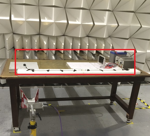
During EMI/EMC Testing, my customer now has problems at 220.15MHz and 408.85MHz, exceeding 7db and 12db respectively.
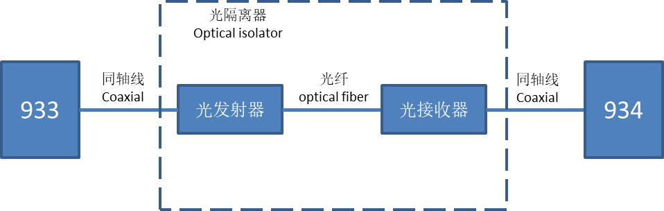
So, I would like to ask specifically, is it necessary to use LVDS fiber isolators to test SERDES such as 933/934?
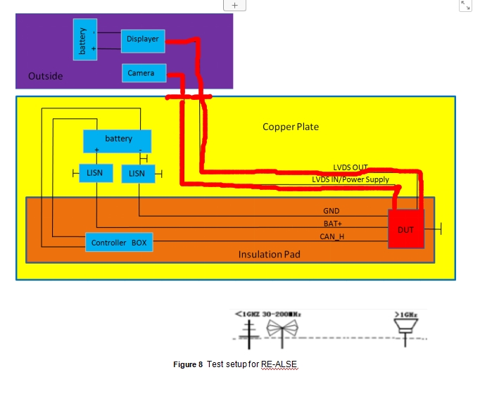
Instead of using optical barriers, customer now use RF coaxial cables, which are connected to the RF port of the waveguide plate of the shielded room, and then connected to the outside of the shielded room.
Could you help us see if there are any problems with the EMI testing environment as following? Thank you!

  • Amile,

    generally the EMC test setup and EMC spec. are required and defined by customers or car OEM.

    Regarding your issue, do you evaluate the UB934-based ECU system RE performance? when you measure the RE performance, You just care for system between transmitter (913a) and receiver with ~2m cable length.

    best regards,

    Steven

  • Hi Steven,

    Actually my customer met the EMI problem under 200MHz before. After the PCB optimization, using stripline and Shield, they solved the EMC/EMI problem under 200MHz.

    However the EMC/EMI problem haven't been solved even after optimizing PCB.At 220.15MHz and 408.85MHz, exceeding 7db and 12db respectively.

    Customer nearly have done all the things they can done to avoid EMC/EMI (PCB optimization and shield).

    Yes, for sure, customer has done the RE test and found that at 220.15MHz and 408.85MHz, exceeding 7db and 12db respectively. I am confused about your answer :when you measure the RE performance, You just care for system between transmitter (913a) and receiver with ~2m cable length. Only need to pay attention to the 933 and cable?

    May I ask whether they need to add Optical isolator to change signal from electrical, optical, electrical? Or do you have  better advice to avoid noise at 220.15M and 408.85MHz?

    Their PCLK is 62.9MHz, 10 bit mode, 62.9MHz /2 = 31.45MHz x7= 220.15MHz ; 62.9MHz /2 = 31.45MHz x13= 408.85MHz

  • sorry I can't understand why you need add the "red cable" in your first figure. again, please check my comments above, and please let's know what you are testing?

    btw, pls check below figure that is used by most car OEM on the RE test.

  • Hi Steven,

    In the picture  you offered, the display,head Unit, camera, 933 and 934, all of them in the shield room. However, as customer feedback, if all of devices are in the shield room, they can't judge whether all the device are working normally because they close the room when testing them in shield room.

    So the normal method they used, is to left the display, head unit and camera in the external environment and put 933/934 in the shield room.

    This testing method lead to using very long coaxial cable, nearly 8m. During so long transmission, it may have bad EMI/EMC performance. 

    So customer asks whether they need to use optical RX and TX to transport and reduce the length of coaxial cable.

    May I ask whether they need to change method A to method B? Or they can put all the device in shield room as your picture shows?

  • please note:

    1. in our test, no panel is required if you measure the RE. my question is why your customer need a panel when measure the RE of camera module?

    2. what is the EMC test guideline that requires 8m cable? please share it with us. as I mentions, car OEMs can define the test setup, different OEMs have different request, but honesty this is the first time that I see 8m cable in the RE test.

    3. regarding if the optical coupler is required, I had replied in the item1, why you need panel, and which module are you testing? now you are working the module test not on the total system test, why you need put all them together in the test?

    reagrds,

    Steven

  • If without the panel, they can't judge whether 933/934 are working normally in the shield room. Because the shield room is close during the whole testing process. When using the panel which can display the video at real time, they can confirm that 933 and 934 work normally so the test makes sense...

    8m is not the requirement. Because they need to connect the external environment to shield room, they have to use so long cable...

  • The RE is for radiated emission, you just care for if the link is brought up..

    Of course you can use the fiber link in the 'NON-DUT" equipment.

    But I think firstly I think you also have many methods to isolate the over-spec. RE is from which section, this is the 1st step to analyze the EMC test issue. You can have many skills here, for example, you just check if the link between ECU and panel has over-spec. RE issue? you also can use one camera system to capture if the panel is ok or not if you measure the BCI.