This thread has been locked.

If you have a related question, please click the "Ask a related question" button in the top right corner. The newly created question will be automatically linked to this question.

DS250DF410: DS250DF410 Technical support

Part Number: DS250DF410

Hi Team,

We have met problem in using DS250DF410, detail as follow:

For now, we can lock the CDR but can not receive the date in receiving end.

can you give me some suggestions in this case? i upload the schematic and register

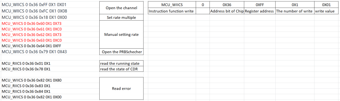
Hope you can help me. Thanks a lot.

  • Hi Team,

    I add the schematic as follow:

  • Hi,

    My inputs below on your register operations.

    • 0x18[6:4] are being set to b000 to force divide by 1. For this write to become effective however 0x09[2] must be set to 1
    • Corrected values for 0x60 thru 0x63
      • 0x60 = 0x74, 0x61 = 0xC0, 0x62 = 0x74, 0x63 = 0xC0
    • See below the write sequences to enable PRBS checker and read PRBS checker count

    Table. Register Writes to Enable PRBS Checker

    STEP

    SHARED/ CHANNEL REGISTER SET

    OPERATION

    REGISTER ADDRESS [HEX]

    REGISTER VALUE [HEX]

    WRITE MASK [HEX]

    COMMENT

    1

    Channel

    Write

    0D

    00

    80

    Turn on the de-serializer

    2

    Channel

    Write

    79

    40

    40

    Set prbs_chkr_en=1

    3

    Channel

    Write

    30

    00

    08

    Set prbs_en_dig_clk=0 to disable the digital clock

    4

    Channel

    Write

    30

    08

    08

    Set prbs_en_dig_clk=1 to enable the digital clock

    5

    Channel

    Write

    30

    10

    10

    Force reload of PRBS checker seed

    6

    Channel

    Write

    30

    00

    10

    Undo force reload of PRBS

    checker seed

    7

    Channel

    Write

    82

    40

    40

    Reset PRBS counters

    8

    Channel

    Write

    82

    00

    40

    Un-reset PRBS counters

    9

    Channel

    Read

    01

    Read PRBS status: Reg_0x01[6]: PRBS pattern polarity detection

    1’b0: Polarity detected is not inverted

    1’b1: Polarity detected is inverted

    Reg_0x01[4]: PRBS sequence detected

    1’b1: Pattern detected

    1’b0: No pattern detected Reg_0x01[3:1]: PRBS detect result

    3’b000: PRBS7

    3’b001: PRBS9

    3’b010: PRBS11

    3’b011: PRBS15

    3’b100: PRBS23

    3’b101: PRBS31

    3’b110: PRBS58

    3’b111: PRBS63

    Table. Register Writes to Read PRBS Checker Error Count

    STEP

    SHARED/ CHANNEL REGISTER SET

    OPERATION

    REGISTER ADDRESS [HEX]

    REGISTER VALUE [HEX]

    WRITE MASK [HEX]

    COMMENT

    1

    Channel

    Write

    82

    80

    80

    Freeze the current error counter

    2

    Channel

    Read

    83

    Reg_0x83[2:0] =

    prbs_err_cnt[10:8]

    3

    Channel

    Read

    84

    Reg_0x84[7:0] =

    prbs_err_cnt[7:0]

    4

    Total error count = ((Reg_0x83 & 0x03) << 8) | Reg_0x84

    5

    Channel

    Write

    82

    00

    80

    Un-freeze the PRBS error counter

    Cordially,

    Rodrigo Natal

    HSSC Applications Engineer

  • I reviewed the schematic and did not find any issue. I'm assuming a valid 25mHz clock signal is being fed to CAL_CLK_IN.

    Regards,

    Rodrigo