This thread has been locked.

If you have a related question, please click the "Ask a related question" button in the top right corner. The newly created question will be automatically linked to this question.

SN65DSI83: SN65DSI EVM: Problem with the LVDS Clock

Part Number: SN65DSI83
Other Parts Discussed in Thread: DSI-TUNER

Hi,

I am currently using the evaluation board of the SN65DSI83.
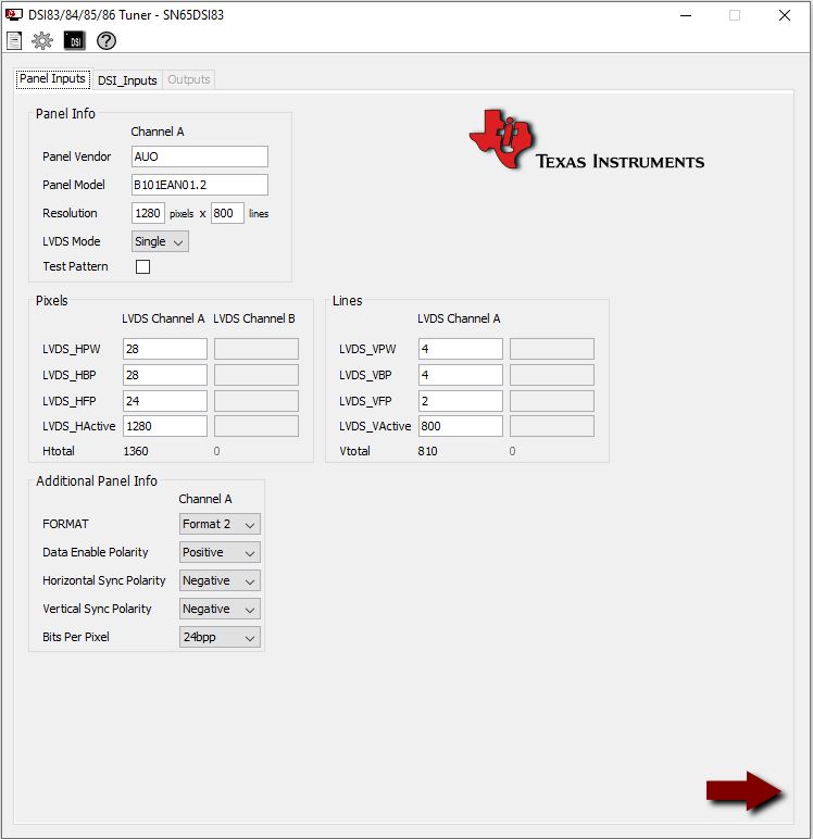
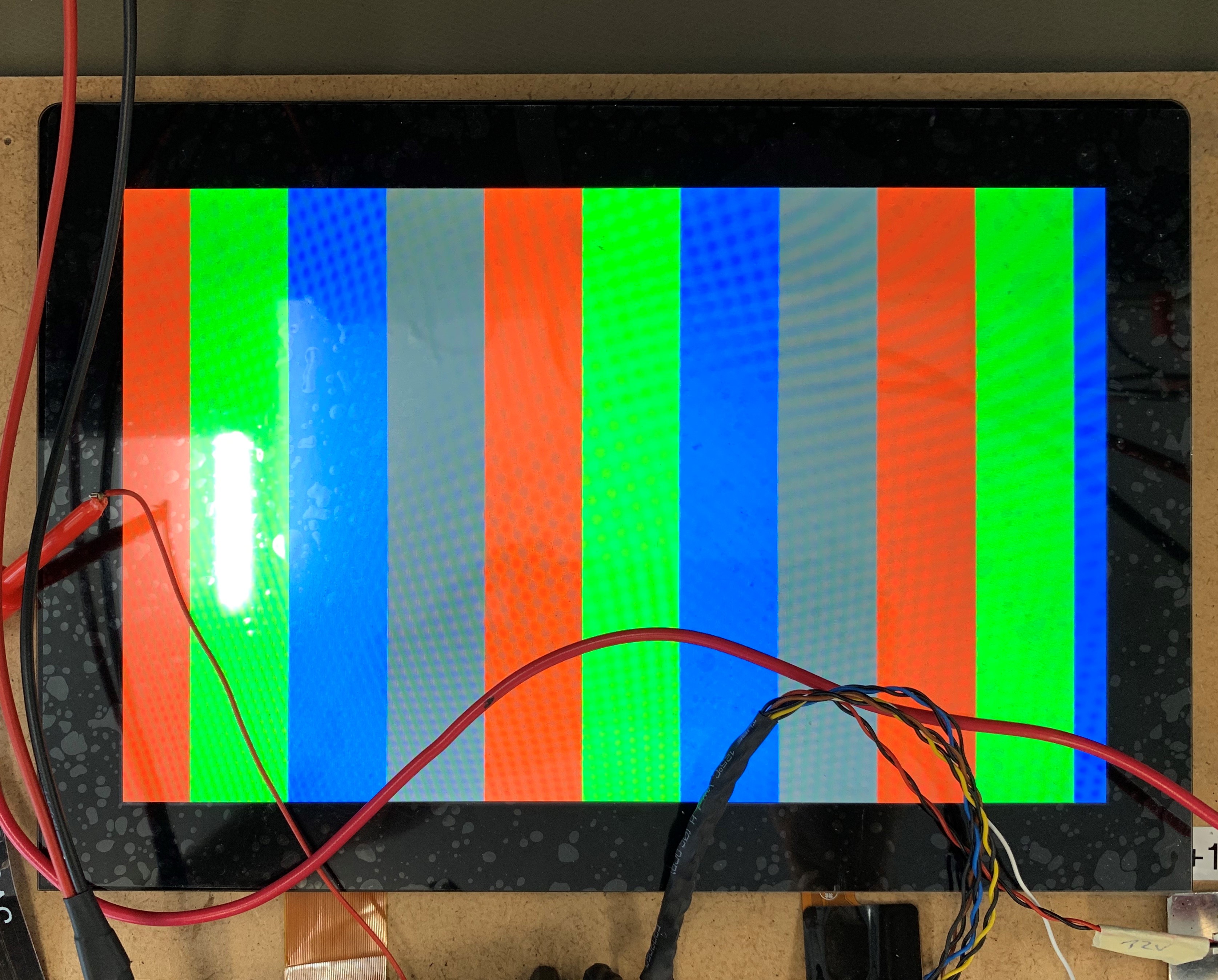
At first I would like to show the test pattern on my display (AUO B101EAN01.2).

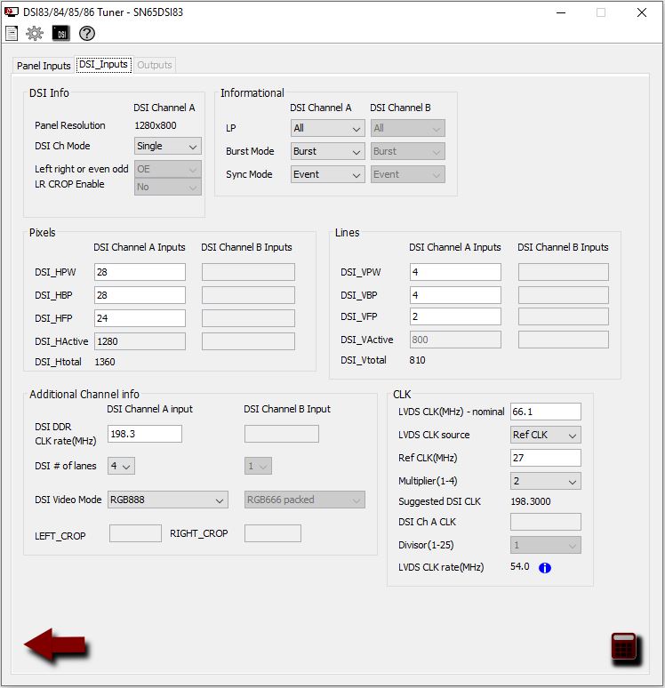
I want to use the 27MHz LVDS_RefCLK for the lvds clock.
(from Y1, have checked the frequency at R33)
If I check the LVDS signals at J6 on channel A, I measure the data signals correctly, but I don't measure a signal at FlatChA_CLKP and FlatChA_CLKN.

For the dsi tuner I have selected the following settings.

Would be glad if someone could help me.
Thanks

  • Important, there is an mistake in the first screenshot!
    I have selected the Test Pattern field of course.

  • Hi Samuel,

    Did you remember to enable the PLL (0x0D)? The output file from the DSI-Tuner does not set this bit as it needs to be set during the initialization sequence. For the test pattern and EVM, you can just set the bit after you've finished writing all of the other registers.

    Regards,

    I.K. 

  • Hi I.K.

    Thanks for your quick answer.
    Yes, I was following the initialization in the datasheet.

    (without Init Seq 2 and Seq 8, does that matter when I use the REFCLK and the test pattern?)

    Do I have to make any changes to the EVM board to display the test pattern (except the jumpers for the external i2c host)?

    Regards,

    Samuel

  • I believe more and more that my EVM (respectively the SN65DSI83) is damaged, because I measure between the FlatChA_CLKN and GND 0R and for the data lines 500R between the line and GND

    This is my current initialization, which runs after a reset via the EN pin.

    <aardvark>
    <configure i2c="1" spi="1" gpio="0" tpower="1" pullups="1"/>
    <i2c_bitrate khz="100"/>

    ======Initialize CSR Register======
    <i2c_write addr="0x2D" count="1" radix="16"> 0A 04</i2c_write> <sleep ms="10"/>
    <i2c_write addr="0x2D" count="1" radix="16"> 0B 02</i2c_write> <sleep ms="10"/>

    <i2c_write addr="0x2D" count="1" radix="16"> 10 26</i2c_write> <sleep ms="10"/>
    <i2c_write addr="0x2D" count="1" radix="16"> 11 00</i2c_write> <sleep ms="10"/>
    <i2c_write addr="0x2D" count="1" radix="16"> 12 5A</i2c_write> <sleep ms="10"/>
    <i2c_write addr="0x2D" count="1" radix="16"> 13 00</i2c_write> <sleep ms="10"/>

    <i2c_write addr="0x2D" count="1" radix="16"> 18 78</i2c_write> <sleep ms="10"/>
    <i2c_write addr="0x2D" count="1" radix="16"> 19 00</i2c_write> <sleep ms="10"/>
    <i2c_write addr="0x2D" count="1" radix="16"> 1A 03</i2c_write> <sleep ms="10"/>
    <i2c_write addr="0x2D" count="1" radix="16"> 1B 00</i2c_write> <sleep ms="10"/>

    <i2c_write addr="0x2D" count="1" radix="16"> 20 00</i2c_write> <sleep ms="10"/>
    <i2c_write addr="0x2D" count="1" radix="16"> 21 05</i2c_write> <sleep ms="10"/>
    <i2c_write addr="0x2D" count="1" radix="16"> 22 00</i2c_write> <sleep ms="10"/>
    <i2c_write addr="0x2D" count="1" radix="16"> 23 00</i2c_write> <sleep ms="10"/>
    <i2c_write addr="0x2D" count="1" radix="16"> 24 20</i2c_write> <sleep ms="10"/>
    <i2c_write addr="0x2D" count="1" radix="16"> 25 03</i2c_write> <sleep ms="10"/>
    <i2c_write addr="0x2D" count="1" radix="16"> 26 00</i2c_write> <sleep ms="10"/>
    <i2c_write addr="0x2D" count="1" radix="16"> 27 00</i2c_write> <sleep ms="10"/>
    <i2c_write addr="0x2D" count="1" radix="16"> 28 20</i2c_write> <sleep ms="10"/>
    <i2c_write addr="0x2D" count="1" radix="16"> 29 00</i2c_write> <sleep ms="10"/>
    <i2c_write addr="0x2D" count="1" radix="16"> 2A 00</i2c_write> <sleep ms="10"/>
    <i2c_write addr="0x2D" count="1" radix="16"> 2B 00</i2c_write> <sleep ms="10"/>
    <i2c_write addr="0x2D" count="1" radix="16"> 2C 1C</i2c_write> <sleep ms="10"/>
    <i2c_write addr="0x2D" count="1" radix="16"> 2D 00</i2c_write> <sleep ms="10"/>
    <i2c_write addr="0x2D" count="1" radix="16"> 2E 00</i2c_write> <sleep ms="10"/>
    <i2c_write addr="0x2D" count="1" radix="16"> 2F 00</i2c_write> <sleep ms="10"/>
    <i2c_write addr="0x2D" count="1" radix="16"> 30 04</i2c_write> <sleep ms="10"/>
    <i2c_write addr="0x2D" count="1" radix="16"> 31 00</i2c_write> <sleep ms="10"/>
    <i2c_write addr="0x2D" count="1" radix="16"> 32 00</i2c_write> <sleep ms="10"/>
    <i2c_write addr="0x2D" count="1" radix="16"> 33 00</i2c_write> <sleep ms="10"/>
    <i2c_write addr="0x2D" count="1" radix="16"> 34 1C</i2c_write> <sleep ms="10"/>
    <i2c_write addr="0x2D" count="1" radix="16"> 35 00</i2c_write> <sleep ms="10"/>
    <i2c_write addr="0x2D" count="1" radix="16"> 36 04</i2c_write> <sleep ms="10"/>
    <i2c_write addr="0x2D" count="1" radix="16"> 37 00</i2c_write> <sleep ms="10"/>
    <i2c_write addr="0x2D" count="1" radix="16"> 38 18</i2c_write> <sleep ms="10"/>
    <i2c_write addr="0x2D" count="1" radix="16"> 39 00</i2c_write> <sleep ms="10"/>
    <i2c_write addr="0x2D" count="1" radix="16"> 3A 02</i2c_write> <sleep ms="10"/>
    <i2c_write addr="0x2D" count="1" radix="16"> 3B 00</i2c_write> <sleep ms="10"/>
    <i2c_write addr="0x2D" count="1" radix="16"> 3C 10</i2c_write> <sleep ms="10"/>
    <i2c_write addr="0x2D" count="1" radix="16"> 3D 00</i2c_write> <sleep ms="10"/>
    <i2c_write addr="0x2D" count="1" radix="16"> 3E 00</i2c_write> <sleep ms="10"/>

    ======Set the PLL_EN bit (CSR 0x0D.0)======
    <i2c_write addr="0x2D" count="1" radix="16">0D 01</i2c_write> <sleep ms="10"/>

    ======Set the SOFT_RESET bit (CSR 0x09.0)======
    <i2c_write addr="0x2D" count="1" radix="16">09 01</i2c_write> <sleep ms="10"/>

    ======LVDS Clock Range and LVDS Clock (0x84) ======
    <i2c_write addr="0x2D" count="1" radix="16" nostop="1"> 0A</i2c_write>
    <i2c_read addr="0x2D" count="1"/>

    ======LVDS Clock Multiplier (0x02) ======
    <i2c_write addr="0x2D" count="1" radix="16" nostop="1"> 0B</i2c_write>
    <i2c_read addr="0x2D" count="1"/>

    </aardvark>

  • Hi Samuel,

    Did you change your settings? In the DSI-Tuner screenshots you have the REFCLK multiplier as 2, but in your script the multiplier is 3. If the REFCLK is 27MHz and you're multiplying it by 3, you get an LVDS CLK of 81MHz, which is outside the clock frequency specification of your panel. 

    Regards,

    I.K. 

  • Hi I.K.

    Yes i changed the settings, I wanted to check if the frequencies on the data lines change (which worked fine).
    So I changed the multiplier only for test purposes, It is set to 2 again.

    But I still measure 0V on the LVDS CLK_N and CLK_P lines.

    Regards, 

    Samuel

  • Hi I.K.

    For testing I set the CHA_REVERSE_LVDS bit to flip the LVDS pins. Now I measure the clock signals but the Y1 signals are missing. So I conclude that there is an error at pin F8/F9 on my SN65DSI83.
    With the turned LVDS lines (I also turned them around on the display) now the test pattern comes, although the Y1 line is missing :)

  • Hi Samuel,

    That's a pretty effective way to debug this issue. I agree, it looks like there's something wrong with F8/F9 on your EVM.

    Regards,

    I.K.