This thread has been locked.

If you have a related question, please click the "Ask a related question" button in the top right corner. The newly created question will be automatically linked to this question.

SN65HVD72: Connecting multiple device

Part Number: SN65HVD72

Hi 

Currently i am using SN65HVD72 for my communication over two boards using UART(baud rate 9600). Both my Primary PCB  and Sensors PCBS use a SN65HVD72,

i would now like to connect multiple sensor PCB's to my Primary PCB. Ideally there will be between 2 to 4 sensors.

I believe for this I would need to make a HUB or Switch PCB , where each sensor would be selected one at a time. 

How must i configure to use multiple SN65HVD72? Is there a specific PCB layout? Can i use one UART port for the SN65HVD72 devices?

  • Hi Dharmesh,

    SN65HVD72 is a RS-485 standard compliant device. This type of transceiver supports multiple nodes connected to a single bus and therefore would not need a switching HUB in order to control which nodes are connected. This functionality is defined in the physical layer of the standard, however the data protocol must be selected by the system designer to ensure that only one node attempts to drive the bus at a time. 

    Please review this technical document - particularly sections 2 "Standard and Features" and 3 "Network Typology" - for an overview and guidelines on multipoint RS-485 design:

    The RS-485 Design Guide


    Let me know if you have any more questions about RS-485 and how it can be implemented in your system.

    Regards,
    Eric

  • Hi Eric

    So if i am correct all the A and B ports are connected, but only one device should be transmitting at any given time, therefore all others would be in RX mode.

    At first i was thinking about making the board with 5 additional SN65HVD72 and a micro controller.

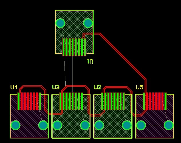
    But now i i guess  my hub switch board would simply be a board with multiple RJ45 connectors(cables i am using). Like a 4 to 1 configuration. The 4 side would all my sensors and 1 would be the connection to the primary connector.  Would this be correct? If so would you have any PCB layout suggestions? I have attached an example of what i am thinking of doing. Please suggest if there needs to be any changes, as i this is very simple design example. 

    i would need to change my firmware protocol so that every device connected would have a unique ID, therefore when a Primary PCB request any information any sensor then only the correct ID sensor would respond. Would this be the correct process?

  • Hi Eric

    The purpose of my design is to test multiple sensors beside one another. Instead of making a fresh PCB as suggested, what would be effect if I was to simply make a proto with jumper wires doing what is shown above  or used the following RJ45 wall plates. Would this have any effect on my device using  the SN65 device.

    www.amazon.co.uk/.../B00BTHRFB0

  • Hi Dharmesh,

    Your understanding here is correct. All A and B terminals can be common. 

    Depending on the data rate, the bus and termination topology may need to be carefully considered to avoid issues due to reflections and ringing. It sounds like the layout you are considering with the PCB would be a star layout (long stubs, difficult to terminate). A jumper wire solution may pose even more trouble with this aspect. However, with a such a slow data-rate, you may be able to ignore these inconsistencies. If you have any concerns about this or run into unexpected communication issues, this may be an area to look into. It may be a good idea to test your design with the jumper wire layout you have and see if it effects communication. If so, we can take a look at scope-shots of the signal to identify probable issues and target a solution.

    I hope this helps. Let me know what you end up going with or if you have more questions about layout and termination topologies.

    Regards,

    Eric

  • My data rate will have  a baud rate of 9600. I am using there jumper wire solution for a quick solution for testing two device at the same time. But would also like to develop a PCB which can do it better. Would you have an example on how the layout should be?  

    Each sensor has its own  SN65HVD72 , i guess the best option would be to daisy chain a sensor onto another sensor, but this may not be possible. 

  • Yes, Daisy chain would likely be best, but seems difficult to implement in this case. If possible, try to keep the wire length between the board and the sensors to a minimum. This way, you could treat them all as short stubs. 

    Do you plant to implement termination on the sensor end? Does the primary connection side have termination?

    Eric

  • Yes each sensor end had 100ohms resistor and length of cable will be a max 15-20 meters.

  • Hi Dharmesh,

    Five 100-ohm terminations is likely going to be too large of a load for the transceiver to drive. Typically a bus will be terminated only at the endpoints (two locations) with 120-ohm (or impedance value of the cable) resistors. The resulting termination load will be around 60-ohms plus the load presented by the transceivers. 

    I termination is already done at the initial node, only one (or possibly none if the data-rate is slow enough) of the sensor nodes should be terminated with a resistor of this value. Alternatively, all 5 nodes could be terminated with larger resistor values to achieve an equivalent load of 120-ohms (five nodes each with 600-ohm termination).

    Would you be able to share a schematic or high-level system overview including cable lengths, SN65HVD72 connections, and termination values at each node? I can review such a document and let you know any concerns or suggestions I may have.

    Regards,
    Eric

  • Hi Eric

    I do not have a high level schematic diagram at the moment, as i am still experimenting with the idea. At the moment each sensor had 100 ohm resistors and so does the primary. 

    I will be experimenting with only two sensors , even though i had chosen 5. The PCB showed 5 purely because i had the space for 5 connectors and thought it  would be a good way to utilise the space.  

    Therefor it i have a primary PCB and 2 additional sensor PCB, would 100 ohms cause any issues? 

    For my application in the future, it is not known how many sensors and user would connect. It could be 1, or 2 or 3 etc. What effect would this have on the termination resistance

    I am using a baud rate of 9600. would that be low enough to avoid using a termination resistor in my application?

    But initially i will be experimenting with two sensors, using the face plate, but then each sensor should be able to connect to the primary board as single device,therefore the termination resistor should be set according to both setups if possible. 

  • Hi,

    Therefor it i have a primary PCB and 2 additional sensor PCB, would 100 ohms cause any issues?

    Three 100-ohm termination resistors would present a load of 33.3-ohms to the device drivers. The device is characterized using a load of around 60-ohms. In Section 7.5 you can see how the Driver differential voltage decreases as the load increases (2.0V at 100-ohm, 1.5V at 60-ohm). Following this trend with lower resistances, it is possible the driver will not be able to drive a valid differential on the bus and communication will fail. Because we characterize for loads near 60-ohms, I recommend choosing termination that would result in an equivalent load close to this value.

    For my application in the future, it is not known how many sensors and user would connect. It could be 1, or 2 or 3 etc. What effect would this have on the termination resistance

    It may be possible to only include termination on one sensor node or no sensor node and still have communication succeed. This depends on many aspects of the system (cable layout, cable quality, cable length, transceivers, environmental noise level, etc.) so I am unsure if this is the best solution. I believe testing these configurations with breakout wiring will show weather this is a possibility worth pursuing. You may also consider including a large termination value on all sensor nodes ( > 1k-ohm). This would still help with reflections somewhat while not over-loading the bus.

    I am using a baud rate of 9600. would that be low enough to avoid using a termination resistor in my application?

    Again, there are many factors that can contribute to a system's susceptibility to reflections. Testing different configurations and viewing the results on an oscilloscope will show which solution is most viable for your particular implementation. 

    Regards,
    Eric

  • Hi Eric

    Thank You for your reply

    As you mentioned that the load on the device would be 33.3 ohms due to three 100 ohms resistors, would this mean that when a single device is connected to my primary PCB the load would be 50ohms? As i am using two 100 ohms. As 60 ohms is required should I use 120 ohms instead? I will always be using Cat5 RJ45 cables.

    For my mentioned application please note, this at the moment is a small test jig type for a project, where I am simply trying to compare the results of two identical sensors and their tolerance. 

    Unfortunately, I do not have an oscilloscope with me at the moment, and I do not want to spend much time experimenting as the purpose is to simply test my sensors, therefore would my best practise be to remove the resistor on both resistors from each sensor or from just one sensor I have connected both sensors at the moment with 100ohms still used and both are communicating with not issues.

    Would it be better to keep the cabling the short as possible e.g. few meters max.


    Please correct me if I am wrong? But for any future multi-sensors application for my setup, it would be better to have some type of hub PCB with multiple SN65HVD72(each sensor connected) and one for the primary pcb. Then have a uC to controls the communication flow. This way I do not have the issue I am having with this test jig.

  • Hi Dharmesh,

    ... would this mean that when a single device is connected to my primary PCB the load would be 50ohms? As i am using two 100 ohms.

    Yes, this would be the case. Total bus load can be calculated as as the parallel equivalent of all termination resistors and transceiver unit loads (typically 15k-ohm per device. Majority in your case caused by termination). 

    As 60 ohms is required should I use 120 ohms instead? 

    It is recommended to use a termination value that matches the impedance of the cable being used. 120-ohms is a common cable impedance and is why the device is characterized for such values. I don't expect there to be a significant impact on performance between 100-ohm and 120-ohm in your case since cable-lengths are short and data-rate is slow. If there is no drawback to switching to the value of the cable's impedance (likely 120-ohms), this would be preferred.

    Would it be better to keep the cabling the short as possible e.g. few meters max.

    Yes. This will decrease ringing by keeping cable parasitics to a minimum. 

    ...it would be better to have some type of hub PCB with multiple SN65HVD72(each sensor connected) and one for the primary pcb.

    This depends on the requirements of your system so I would not be able to recommend a best approach. However, with slow data-rates and short cable-lengths, I do not expect a less-than-ideal cable layout to present significant communication problems. 

    Unfortunately, I do not have an oscilloscope ... This way I do not have the issue I am having with this test jig.

    If problems do arise, it should reported by the software (depending on the implementation used). Parity checks would ensure any data corruption can be identified and you can proceed to debug physical layer issues.

    Let me know how the setup turns out and if you encounter any issues.

    Regards,
    Eric

  • Dear Eric

    It seems to be working well,so far . This setup was for used for a small test i conducting with multiple sensors.

    Before closing this case, i would like to show you a diagram that i will prepare in next few days of what i intend to do for my multi device hub board.

  • Hi Dharmesh,

    Great news!

    Let me know when it is ready and I can review the diagram.

    Regards,
    Eric