This thread has been locked.

If you have a related question, please click the "Ask a related question" button in the top right corner. The newly created question will be automatically linked to this question.

TPS65983B: PD firmware assistance for loopback

Part Number: TPS65983B
Other Parts Discussed in Thread: TPS65982

Hi,

I have a loopback design based on Intel input for HVM.  I have included a block diagram for clarity.

The design includes the TPS65983B PD controller and spi flash.  There is no Thunderbolt device in the design.

I have built PD firmware using the TPS65983 Thunderbolt Application Customization Tool version 4.12.  The firmware was built using the Bus-powered Device template.

This results in board power up and the loopback device "wakes-up" the USB3.1 Host controller in Alpine Ridge on a host system.  I need it to "wake-up" the Thunderbolt Controller which is not happening.

My question is:

1. Is there a way to build the PD firmware so that the PD controller identifies itself as a Thunderbolt device?

  • Hello Daniel,

    The expert covering this device is currently in training but will get back to you shortly. Please expect a delay in his response, and thank you in advance for your patience.

  • Hi Daniel,

    Can you describe in more detail how the PD would identify itself as a TBT device or what is required to wake up the TBT controller?

    The TPS65983B configurations and firmware are constrained to the set of Intel TBT reference designs. A change outside these requires coordination outside of TI.

    Regards,

    Scott

  • Hi Scott,

    Here is a little more background:

    This is an Intel ref design for high volume manufacturing test.  It is designed to test Alpine Ridge host interfaces via the loopback mechanism.  The note from Intel states that this is a HW & FW reference design provided by the PD controller vendor and to contact the PD controller vendor for the latest reference design info (HW & FW).  The reference design provided by Intel uses the TPS65982 with references to the TPS65983.  I used the TPS65983B in my design.

    Your question about "what is required to wake up the TBT controller?" is exactly what I'm asking.  I have boards in hand and have tried different FW configurations and have not been able to "wake-up" the Host's TBT controller, Alpine Ridge, in this case.  It just "wakes-up" the USB controller in the Host's Alpine Ridge interface.

    FW configurations include PD firmware only and PD firmware merged with Alpine Ridge device firmware.

    Let me know if you need any more detail.

    Thank you,

    Daniel

  • HI Daniel,

    Thank you for the update. Let me add my comments. I am also checking into this application and will have another update tomorrow.

    This is a standalone PD application and PD FW alone is fine.

    My schematic also references the TPS65982. Can I ask why you substituted the TPS65983B?

    Have you checked for activity on CC1/CC2 and VBUS or that the PD has booted FW and is active? A low speed scope trace is sufficient here.

    Regards,

    Scott

  • Hi Scott,

    I used the TPS65983B because I'm already using this device on the host system that I am trying to test.

    As for activity on CC1/CC2, etc.  I've attached a Trace capture that shows activity.

    Thanks,

    Daniel

  • Hi Daniel,

    The PD trace shows activity without a contract or connection because no PD message gets a GoodCRC.

    Before we move on, can you verify that the TPS65983B is the source of the messages and that the device has booted correctly?

    Thanks,

    Scott

  • Hi Scott,

    Your right, I did some more investigation today and I am not getting any response from the SINK (Loopback).  Everything in that trace is from the Source.  The traces that I capture look the same with a blank SPI flash and with a programmed SPI flash.  This is why I suspect the PD firmware has not been built properly.

    I'm connected as described here.

    "When the voltage on BUSPOWERZ is in the VBPZ_DIS range (when BUSPOWERZ is tied to LDO_3V3 as in Figure 32), this indicates that the TPS65983B will not route the 5 V present on VBUS to the entire system. In this case, the TPS65983B will load SPI-connected flash memory and execute this application code. This configuration will disable both the PP_HV and PP_EXT high voltage switches and only use VBUS to power the TPS65983B."

    I have verified with a scope that i'm getting SPI_CLK activity and a short burst of activity on SPI_MOSI.  There is no activity on SPI_MISO.  I also have valid LDO_3V3, LDO_1V8A, and LDO_IV8D power rails from the PD controller.

    For the PD Firmware, I've been using the Bus-powered Device template and the tps65983_v0006.63.00.bin as my firmware base image which I have been saving as a Low Region binary.

    Thanks,

    Daniel

  • Hi Daniel,

    I am concerned there is no SPI MISO activity.

    Have you followed the reference design a set Debug_ctrl 1 and 2 high? These need to match the settings in the firmware image.

    How are you placing the image in the Flash? The initial image needs to be a full flash image if transferred with an external tool or set with the '83B Config GUI. A Low Region binary flashed with an external tool (such as Total Phase Aardvark) will be incomplete.

    Regards,

    Scott

  • Hi Scott,

    I checked both DEBUG_CTRL1 & 2,  both are pulled high and match my firmware image.

    I am using the Ardvark Flash Center to flash the device but I have been using the low-region binary that the application customization tool creates.

    I saved a Full Flash Image and used the Ardvark to deploy it today.  The behavior is now different.

    When the loopback is plugged into a host system, the VBUS voltage toggles on and off at 1.4Hz.  I've probed on MOSI and MISO both and now see activity but that activity gets reset every time VBUS toggles.

    Have you see this behavior?  Do I possibly still have something set wrong in the Firmware that is causing this?

    Thanks,

    Daniel

  • Hi Daniel,

    The flash image format was for sure an issue and that is now fixed.

    The PD is being disconnected and loses power when Vbus goes low. When Vbus goes high, the PD starts to boot again and accesses the flash.

    Have you made any changes to the dead battery RP section of the schematic?

    Have you probed CC1/CC2 to check for Rp/Rd before and after Vbus disconnect?

    Regards.

    Scott

  • Hi Scott,

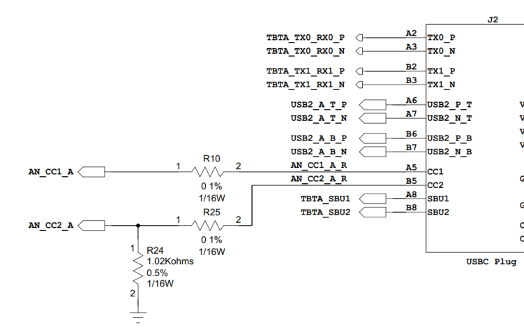
    Good catch.  I found a discrepancy in the docs that I have that noted an alternate configuration for CC2 when using e-Marker cables.  This alternate config wants a Pd on CC2 as seen here.

    If I remove the 0-ohm at R25, the PD negotiates as it should but the loopback device still isn't identifying itself as a PCIe device.  I don't get the EnterMode message when capturing the PD trace.

    Thanks for all the help,

    Daniel 

  • Hi Daniel,

    What do you see in the current PD trace that leads to a failing Enter Mode? Can you describe what PCIe id would look like? For PD alt mode entry, I expect to see a predefined alt mode discovery sequence (Display Port or Thunderbolt) or a user defined Alt Mode.

    Regards,

    Scott

  • Hi Scott,

    I've included my current PD trace.  I don't see the the EnterMode request from the host like I do when I plug in other thunderbolt peripherals.

    I also get a Windows pop-up message stating the following: "Thunderbolt device functionality might be limited... Select message for more info."

    What I expect to happen is Windows should initialize the loop-back as a PCIe device and occupy a PCIe Root Port with an ID of 0x1577.

    Thanks,

    Dan

  • Hi Dan,

    The trace section itself looks okay. Does the sequence stop there or go on? I expect SOP' discovery to continue to Discover SVID and Mode to determine if SOP' supports Thunderbolt mode or not. Generally there will not be an Enter Mode sequence until the PD determines if the SOP' supports TBT or not. If not, we could then see a DP Enter Mode.

    Regards,

    Scott

  • Hi Scott,

    The sequence continues but only includes REQs for DiscIdentity.  No other activity is observed.

    I built an image today using the Apex Creek project in the Application Customization Tool.  The Apex Creek project includes more SVIDs than the Bus-Powered Device project.  I don't get an Enter Mode REQ with that firmware either.  Iv'e included two Sink DiscSVID data structures for comparison.  The first one built using the Bus-Powered Device project showing only one SVID type and the second image built using the Apex Creek project which shows two SVID types which includes a DisplayPort SID.  Neither of these firmware traces include an Enter Mode CMD.

    Firmware based on Bus-Powered Device

    Firmware based on Apex Creek 

    Thanks,

    Dan

  • Hi Dan,

    For this reason I recommend using the TPS65982 as indicated in the schematic.

    Regards,

    Scott

  • Hi Scott,

    The Application Customization Tool for the TPS65982 has the Intel Loopback Board project under reference designs.

    This project builds firmware that allows the board to enter loopback mode.

    Thanks for all your help.