Part Number: DS110DF111
Other Parts Discussed in Thread: USB2ANY, DS125DF111,
Hi
I have DS110DF111 in my board. I have made a i2c connection to this device and connected to USB2ANY adaptor. I am able to peek poke of registers from Sigcon tool.
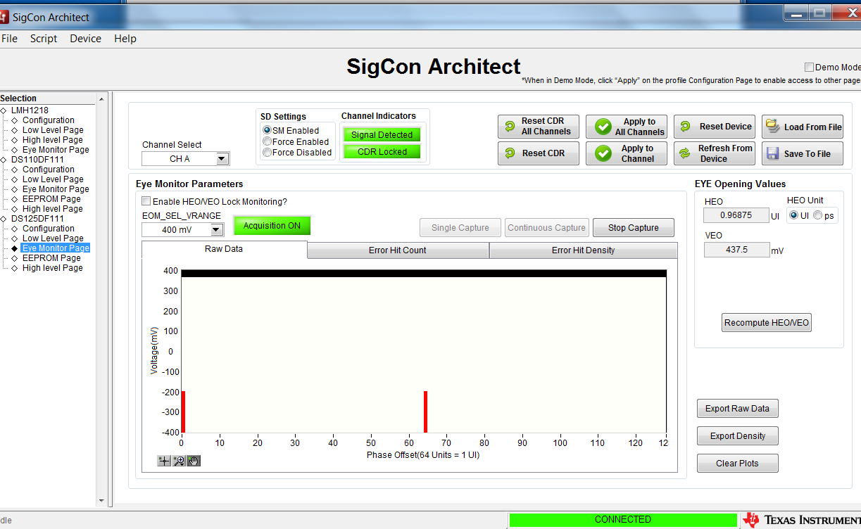
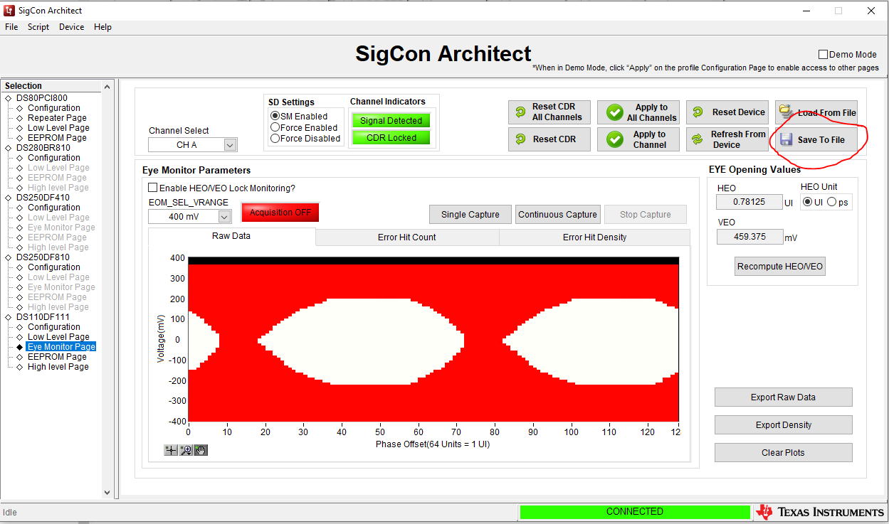
While I was trying to check the eye using sigcon tool, the eye pattern is always blank even though the opening values is getting updated ( Example HEO – 0.78125 UI and VEO – 325mv). Is there any sequence of registers we need to write to display eye . I tried below sequence as per the datasheet, but didn’t help.
0x3E <- 00
0x2C <- 32
0x11 <- no change
0x11 <- 00
In one of the document (snlu126c), I could see that there was tab in the same eye opening window that shows the data rate. I don’t see that in my tool. This display would help me to confirm the data rate observed is 10.3125Gbps. If we don’t have this option for ds100df111 profile , how else can I confirm the data rate ?
--
Krish