This thread has been locked.

If you have a related question, please click the "Ask a related question" button in the top right corner. The newly created question will be automatically linked to this question.

HD3SS3220: HD3SS3220 and RS485 protocole

Part Number: HD3SS3220
Other Parts Discussed in Thread: SN65HVD33,

Hello everyone,

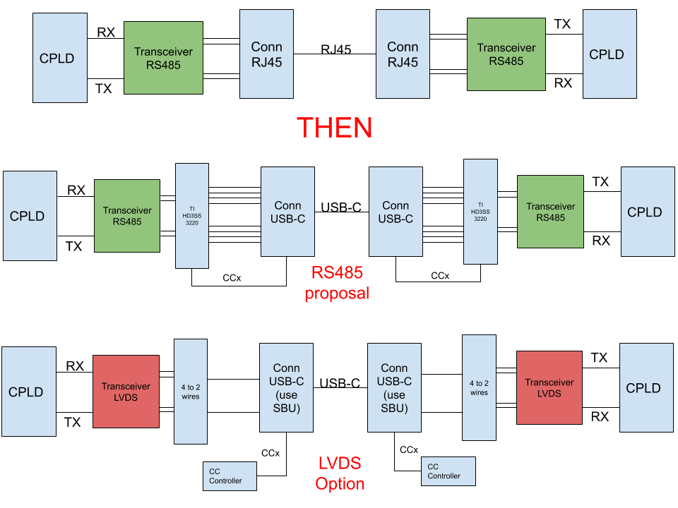
We used, for an old design, a RS485 transceiver with a RJ45 cable for the communication via a differential pair between 2 card (an 2 CPLD).

We want to replace our RJ45 connector by a USB Type-C connector o be more "up-to-date".

The idea is using a TI SN65HVD33 for the RS485 protocole and a TI HD3SS3220 for the management of the USB Type-C connector (Mux and CC detector).

But actually, we have some doubt about the AC coupling capacitor on the USB line (not really RS485 compliant) and we don't know if it's possible to use this configuration.

Do you have any tips about that ?

Just a little recap : CPLD --> RS 485 transmitter (TI SN65HVD33) --> Passive switch USB-C (TI HD3SS3220) --> USB-C connector

Thank you or your future help.

Thomas

HD3SS3220

  • Hi Thomas,

    Could you give me more details on your application, what is the intended end use? Is this meant to be USB compliant or is this device only meant for internal use?

  • Hi Malik,

    It's only for internal use but we juste want to prevent misconnecting between our equipment and a third party one witch really use usb type-c.
    It's the reason we want to be a minimum USB-C compliant.

    Someone talk to me of LVDS insteed of RS485. Any opinion ?

  • Hi Thomas,

    I can see two options here...

    1. Instead of using the High Speed Lane (TX1/2, RX1/2), use both SBU lines to communicate over the Type C connector. The SBU (Sideband Use) are actually meant for this person to carry non-USP/DP signals across the connector. Only two wires would be used in this case, maybe more ideal for LVDS. Typically in the SBU lines are only used in Alternate mode applications (DP) since this is mainly internal you should not have to worry about this. In this case you can get away by simply connecting as a simple UFP/DFP to indicate a connection has been made a decode the orientation of the connector.
    2. If you want to use the High Speed Data lines to have more than two wires to work, you should use Debug Accessory mode. This is a state with a CC controller to display (through I2C) that debug accessory has been connected. Please review section 7.3.8 Debug Accessory of the Hd3SS3220 datasheet to get some more details on this. You can think of the mode as a "special" connection where all the wires can take on a different role than typical USB-C (except for Vbus). Both LVDS and RS485 can be used in this scenario. In this case, orientation can a bit tricky as it cannot be determined by the CC lines but can be determined by the USB 2 lines (USB plugs only have 1 pair of D+/D-). However you will lose your USB 2 capability.  

    LVDS may be a better fit depending on your data rate the power you want to consume with you transmitter. Is your device meant to both send and receive data?

  • Hi Malik, 

    First thank you for the time you used to help me.

    Then, i'll use draw to show you what i've understood.

    It's what you thing with the option 1 ?

    For information, the rate is 1M/s but, in the old configuration it was only 200k/s 

  • Hi,

    Could you also describe the target cable length? Option 1 seems to be workable. 1 Mbps is definitely in the range of HD3SS3220 switching capability.

  • The cable is probably around 1m length not really more.

  • Hi,

    Option can work here I would make sure the RS485 transceiver Vpp and Vcm are within the range of HD3SS3220. LVDS would also work in option 1 and maybe more compatible with HD3SS3220. 

  • Thanks Malik,

    I think i'll try the LVDS option. Maybe the easiest way to do what I want.

    Just need to find the rights components know ^^

    I'll keep you in touch.