This thread has been locked.

If you have a related question, please click the "Ask a related question" button in the top right corner. The newly created question will be automatically linked to this question.

TL16C752D: about LCR and MCR register

Guru 29720 points
Part Number: TL16C752D

Hi Team,

I would like to ask the following questions.
1) There is no description when LCR[5]=0. Is there any information?


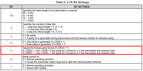
2) LCR[7] shows the following in datasheet.

Does "Divisor latch enable" indicate enabling the following operation?

(datasheet page 37)
8.5.12 Divisor Latches (DLL, DLH)
Two 8-bit registers store the 16-bit divisor for generation of the baud clock in the baud rate generator.
DLH, stores the most significant part of the divisor. DLL stores the least significant part of the division.
DLL and DLH can only be written to before sleep mode is enabled (that is, before IER[4] is set).

3) MCR[3] shows the following in datasheet.
Does IRQ(A-B) indicate INT(A-B)? There is no description about IRQ(A-B) in datasheet.
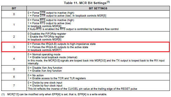

Best Regards,
Yaita

  • Hi Yaita,

    1) LCR[5] defines selected Forced Parity. I believe when this bit is set, it will force the value of the parity bit according to the value of LCR [4]. When bit 5 is not set (LCR[5] = 0), the parity bit will be generated according to the behaviors described in LCR[3:4]. 

    2) The main use for LCR[7] is to control register access to DLL and DLH for divisor values. The description reflects the accessibility of these registers based on the value of LCR[7]. Figure 26 illustrates this behavior. 

    3) IRQ(A-B) is equivalent to INT(A-B). I agree this is not intuitive. 

    Let me know if you have any more questions.

    Regards,
    Eric