Because of the holidays, TI E2E™ design support forum responses will be delayed from Dec. 25 through Jan. 2. Thank you for your patience.

This thread has been locked.

If you have a related question, please click the "Ask a related question" button in the top right corner. The newly created question will be automatically linked to this question.

TCAN1042H: Replace SN65HVD231DR

Part Number: TCAN1042H
Other Parts Discussed in Thread: AM3352, SN65HVD231, TCAN337G, TCAN330G

Dear Team,

The TCAN1042 can P2P replace SN65HVD231DR, right?

The customer replaces the SN65HVD231DR but it didn't work.

Originally the SN65HVD231DR work well on the system, we replace it by TCAN1042 directly.

The CAN frequency is 125kHz, can you check what is wrong here?

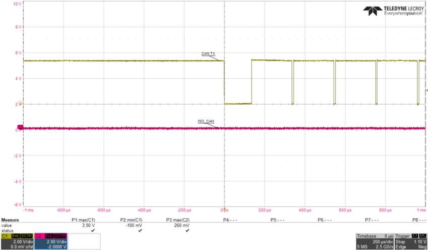
The input signal is CH1 from AM3352, CH2 is after TCAN1042.

BR

Kevin

  • Kevin,

    The TCAN1042 family of transceivers is based on a VCC supply of 5V and thus a 5V CAN bus and logic levels. The SN65HVD231 is a 3.3V VCC design with a 3.3V CAN bus and 3.3V logic levels. What is the supply level on your VCC pin when the TCAN1042 is populated?

    What pin is the waveform labeled ISO_CAN? RXD?

    On your oscilloscope screenshot it looks like your TXD signal is never going below 2V, which means it is never crossing the threshold to a logic low on the TCAN1042 (0.8V). Along with the previous questions I have, was the TXD signal going lower when using the SN65HVD231?

    Regards,

  • Dear Eric,

    Thanks for the prompt response!

    We will try the TCAN1042 with 5V.

    1. Do we have CAN FD IC can support 3.3V which can replace SN65HVD231 directly?

    2. CH2 is a differential signal of PIN6,7 CANH CANL

    3. The CH1 signal is 0~3.3V, so id did pass the logic of threshold.

    BR

    Kevin

  • Kevin,

    Ah yes, if there is only 3.3V at the VCC of TCAN1042, then the device hasn't passed the undervoltage threshold and thus isn't powered on. This is why the CANH and CANL pins aren't responding

    1. Yes, the TCAN330G or the TCAN337G will both work with your current schematic and work with data rates up to 5Mbps.

    2. Understood.

    3. Yes I see it now, the lowest value of the signal is at the 2V marker on the oscilloscope. I was a little confused.

    Please let me know if you have any other questions.

    Regards,