This thread has been locked.

If you have a related question, please click the "Ask a related question" button in the top right corner. The newly created question will be automatically linked to this question.

AM26C31: Recommended Resistors and capacitors

Part Number: AM26C31
Other Parts Discussed in Thread: AM26C32

Hi,

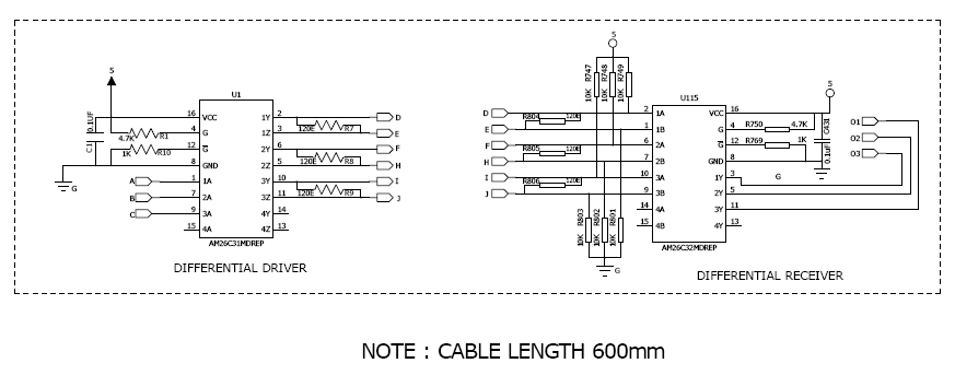
I am using AM26C31MDREP as a differential driver and AM26C32MDREP as a differential receiver, With 5V single-ended signal input for AM26C31MDREP and expected 5V single-ended output from AM26C32MDREP. Can anyone let me know what are the recommended resistors and capacitors required for the above configuration, the cable length between differential drive and receiver will be maximum of 600mm. Please post any reference design.

With regards,

Sivakrishna

  • Hi Sivakrishna,

    I don't see a figure that I believe you referred to: "for the above configuration". 

    Termination resistors should be selected based on node layout and cable characteristic impedance. Typical values are between 80 to 120-ohms. This article elaborates on termination and how it can benefit your system:
    RS-485 basics: When termination is necessary, and how to do it properly

    Suggested values for local decoupling or bypass capacitors are 0.1uF on both device datasheets.

    I hope this information is helpful. If it did not answer your question, please try posting the configuration figure again.

    Regards,
    Eric


  • Hi,

    Here I am attaching the images of my schematic verify it.

    Note if the input signal at the driver is LOW output signal at the receiver should also be LOW

    With regards,

    Srikrishnarecever.pdf

  • Hi Sivakrishna,

    Thanks for sharing the image. My comments are below:

    1) Unused digital inputs should not be left floating. I recommend tying U1:4A (pin15) to Vcc or GND. This may optionally be done through a resistor. It is alright to leave unused digital output pins and bus pins floating (U1:4Y-4Z, U115:4A-4B-4Y are all fine). 

    2) I noted that the fail-safe biasing network near the receiver does not appear to be strong enough to pull the bus above the positive input threshold Vth+. The network will provide stability and slight noise immunity, though it will still leave the bus hanging in the indeterminate zone. However, because AM26C32 implements internal fail-safe circuitry, it is not necessary to increase the strength of this network to achieve this. 

    3) The polarities of the driver and receiver do indeed match. "Note if the input signal at the driver is LOW output signal at the receiver should also be LOW" This will be true given the current configuration. 

    Let me know if you have any other concerns. 

    Regards,
    Eric