This thread has been locked.

If you have a related question, please click the "Ask a related question" button in the top right corner. The newly created question will be automatically linked to this question.

DS90UB953-Q1: Some questions about UB953&UB954...

Part Number: DS90UB953-Q1

Dear Sirs,

Below is customer function block and some questions.

Please help to input your comments.

Thanks.
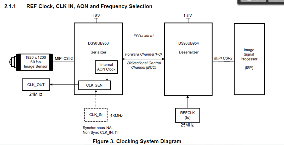
The questions are:

1. If customer want to change the CLK_OUT of 953 side from 24MHz to 50MHz, what registers and value that customer need to set?

Now 953 set to MODE2 and 954 set to MODE0

2.  for different resolution camera, did customer need to prepare different setting for each of them? The display is 1280x100x60p 4 lane MIPI input panel. 

a. camera with 1280x1080x60p 4 lanes MIPI output 

b. camera with 1280x720x30p


3. There is MCU in 954 side, if the customer want to set passthrough mode to control 953, how and what registers that customer need to set?

4. what is the 953 and 954 initial code? Did customer need to set different setting for different resolution?

Thanks. 


  • Hi Peter,

    1. If customer want to change the CLK_OUT of 953 side from 24MHz to 50MHz, what registers and value that customer need to set? Register 0x06 and 0x07 in the 953. Check table 6 in the datasheet for the equation.

    Now 953 set to MODE2 and 954 set to MODE0

    2.  for different resolution camera, did customer need to prepare different setting for each of them? The display is 1280x100x60p 4 lane MIPI input panel. Are both cameras using 4 lane mode? If so, no additional registers are needed. You can change the number of lanes in reg 0x02 in the 953.

    a. camera with 1280x1080x60p 4 lanes MIPI output 

    b. camera with 1280x720x30p


    3. There is MCU in 954 side, if the customer want to set passthrough mode to control 953, how and what registers that customer need to set?

    Set Aliases on the Deserializer:

    - Des reg 0x4C: Select the right RX port to write

    - Set/Check real I2C addresses

    - Reg 0x5B SER DEVICE ID: Set the real serializer I2C address. This is typically loaded already

    - Reg 0x5D SlaveID[0]: Set the real CMOS sensor I2C address

    - Reg 0x5C SER_ALIAS_ID: Set the alias serializer I2C address

    - Reg 0x65 SLAVE_ALIAS_ID[0] (camera alias ID): Set the alias CMOS sensor I2C address

    Communicate to the 953/imager using their alias IDs.

    4. what is the 953 and 954 initial code? Did customer need to set different setting for different resolution?

    As long as mode strap is correct, the ports are selected (954 reg 0x4C), and back channel is correct (954 reg 0x58). The devices should lock. No registers are needed to set different resolution.

    Best,

    Jiashow