Part Number: DS90UB941AS-Q1
Hello,
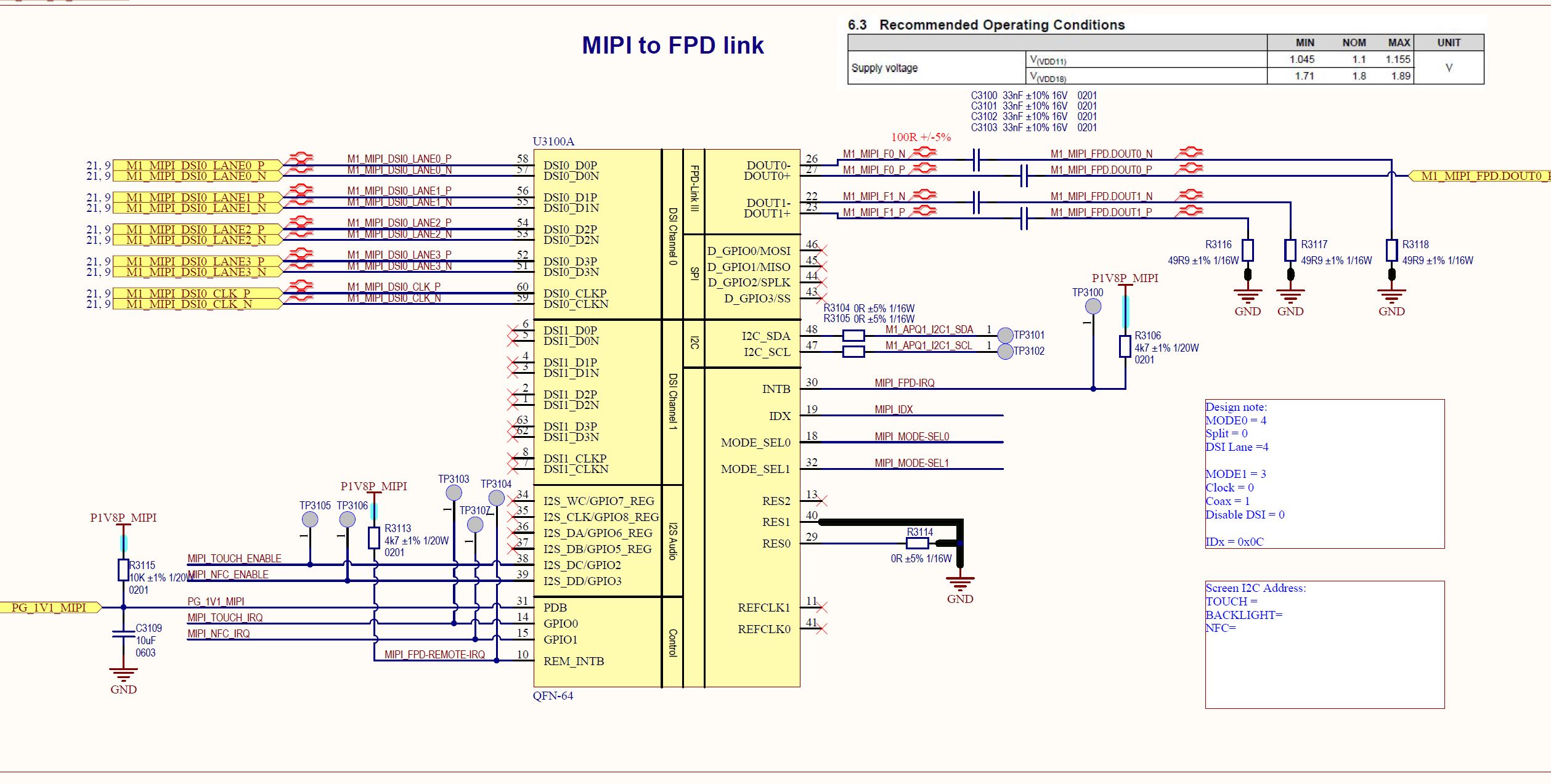
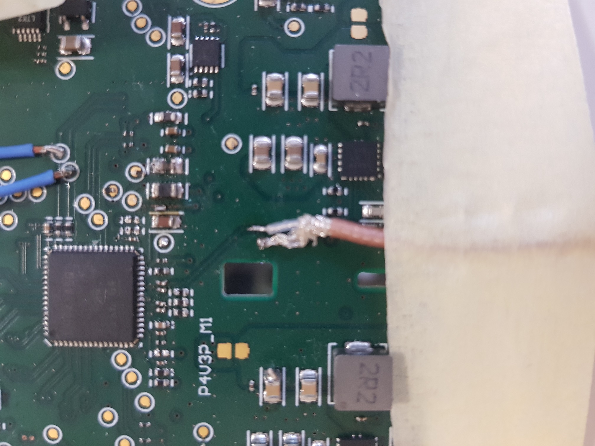
Our SerDes configuration is : DS90UB941 <=> DS90UB948
The I2C communication between serializer and deserializer is not constant.
We can see that when doing a i2cdetect that some addresses are sometimes disappearing on bus.
-
sdm845:/ # i2cdetect -y -r 2
-
0 1 2 3 4 5 6 7 8 9 a b c d e f
-
00: -- -- -- -- -- -- -- -- -- 0c -- -- --
-
10: -- -- -- -- -- -- -- -- -- -- -- -- -- -- -- --
-
20: -- -- -- -- -- -- -- -- UU -- -- -- UU -- -- --
-
30: -- -- -- -- -- -- -- -- -- -- -- -- 3c -- -- --
-
40: -- -- -- -- -- -- -- -- -- -- -- -- -- -- -- --
-
50: -- -- -- -- -- -- -- -- -- -- -- -- -- -- -- --
-
60: -- -- -- -- -- -- -- -- -- -- -- -- -- -- -- --
-
70: -- -- -- -- -- -- -- --
-
sdm845:/ # i2cdetect -y -r 2
-
0 1 2 3 4 5 6 7 8 9 a b c d e f
-
00: -- -- -- -- -- -- -- -- -- 0c -- -- --
-
10: -- -- -- -- -- -- -- -- -- -- -- -- -- -- -- --
-
20: -- -- -- -- -- -- -- -- UU -- -- -- UU -- -- --
-
30: -- -- -- -- -- -- -- -- -- -- -- -- -- -- -- --
-
40: -- -- -- -- -- -- -- -- -- -- -- -- -- -- -- --
-
50: -- -- -- -- -- -- -- -- -- -- -- -- -- -- -- --
-
60: -- -- -- -- -- -- -- -- -- -- -- -- -- -- -- --
-
70: -- -- -- -- -- -- -- --
-
sdm845:/ # i2cdetect -y -r 2
-
0 1 2 3 4 5 6 7 8 9 a b c d e f
-
00: -- -- -- -- -- -- -- -- -- 0c -- -- --
-
10: -- -- -- -- -- -- -- -- -- -- -- -- -- -- -- --
-
20: -- -- -- -- -- -- -- -- UU -- -- -- UU -- -- --
-
30: -- -- -- -- -- -- -- -- -- -- -- -- 3c -- -- --
-
40: -- -- -- -- -- -- -- -- -- -- -- -- -- -- -- --
-
50: 50 -- -- -- -- -- -- -- -- -- -- -- -- -- -- --
-
60: -- -- -- -- -- -- -- -- -- -- -- -- -- -- -- --
-
70: -- -- -- -- -- -- -- --
This causes touchscreen to not always respond when the user is touching the screen and also backlight and NFC do not initialize properly.
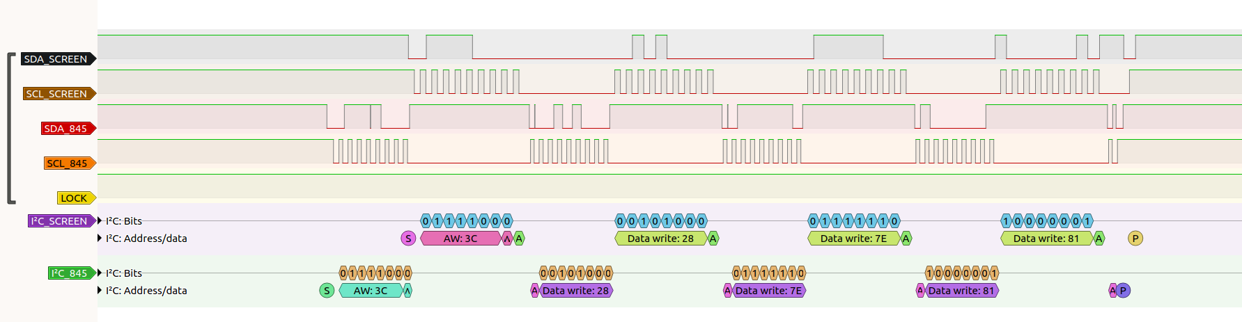
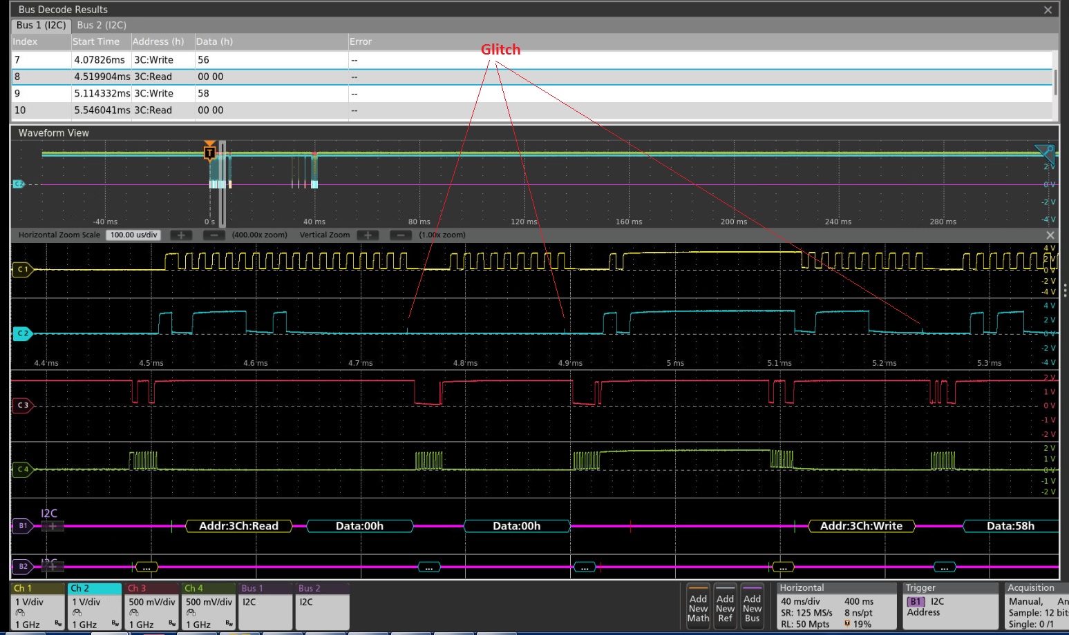
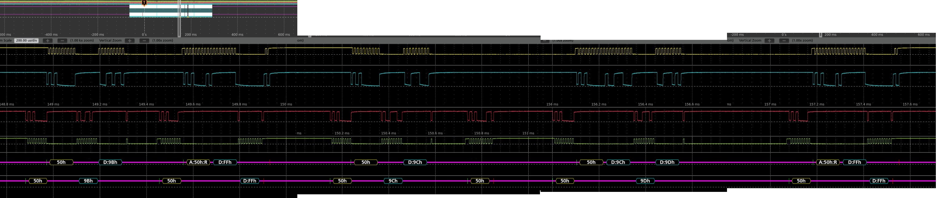
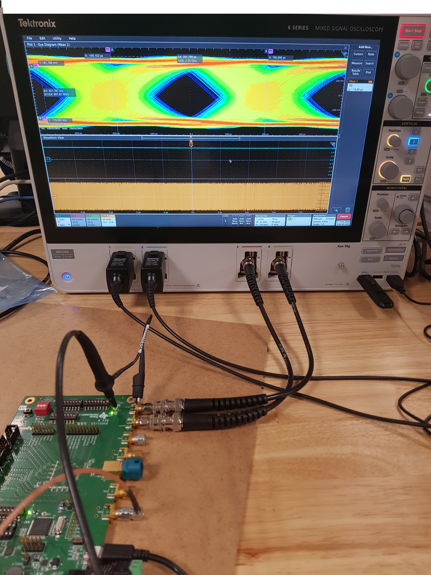
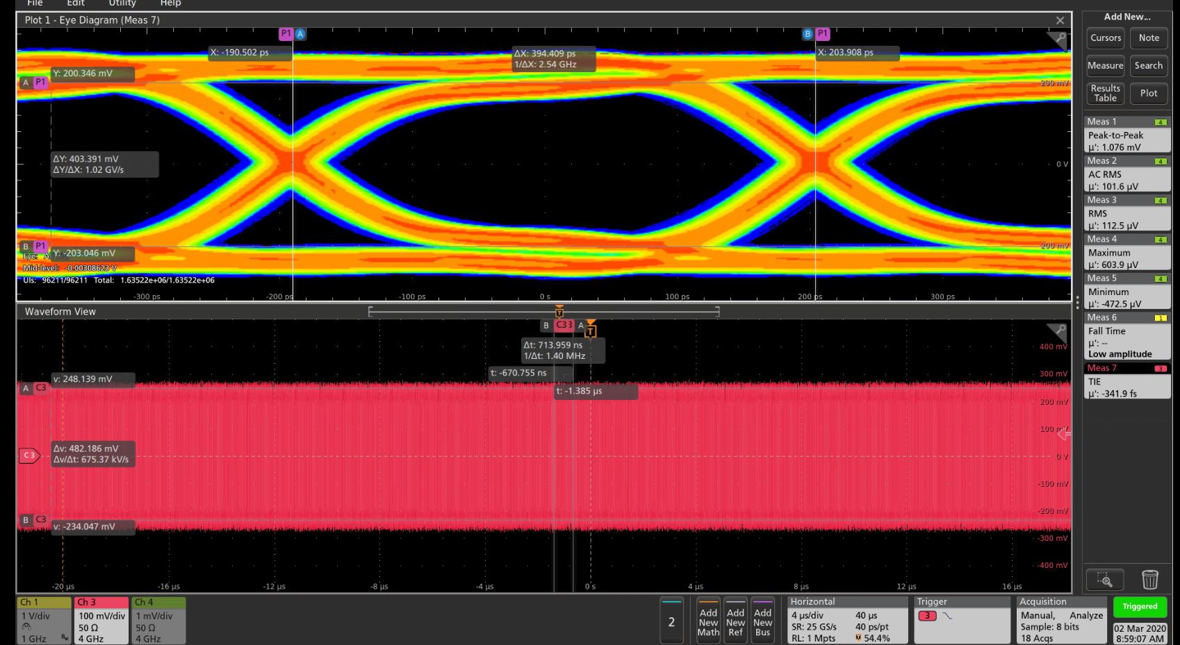
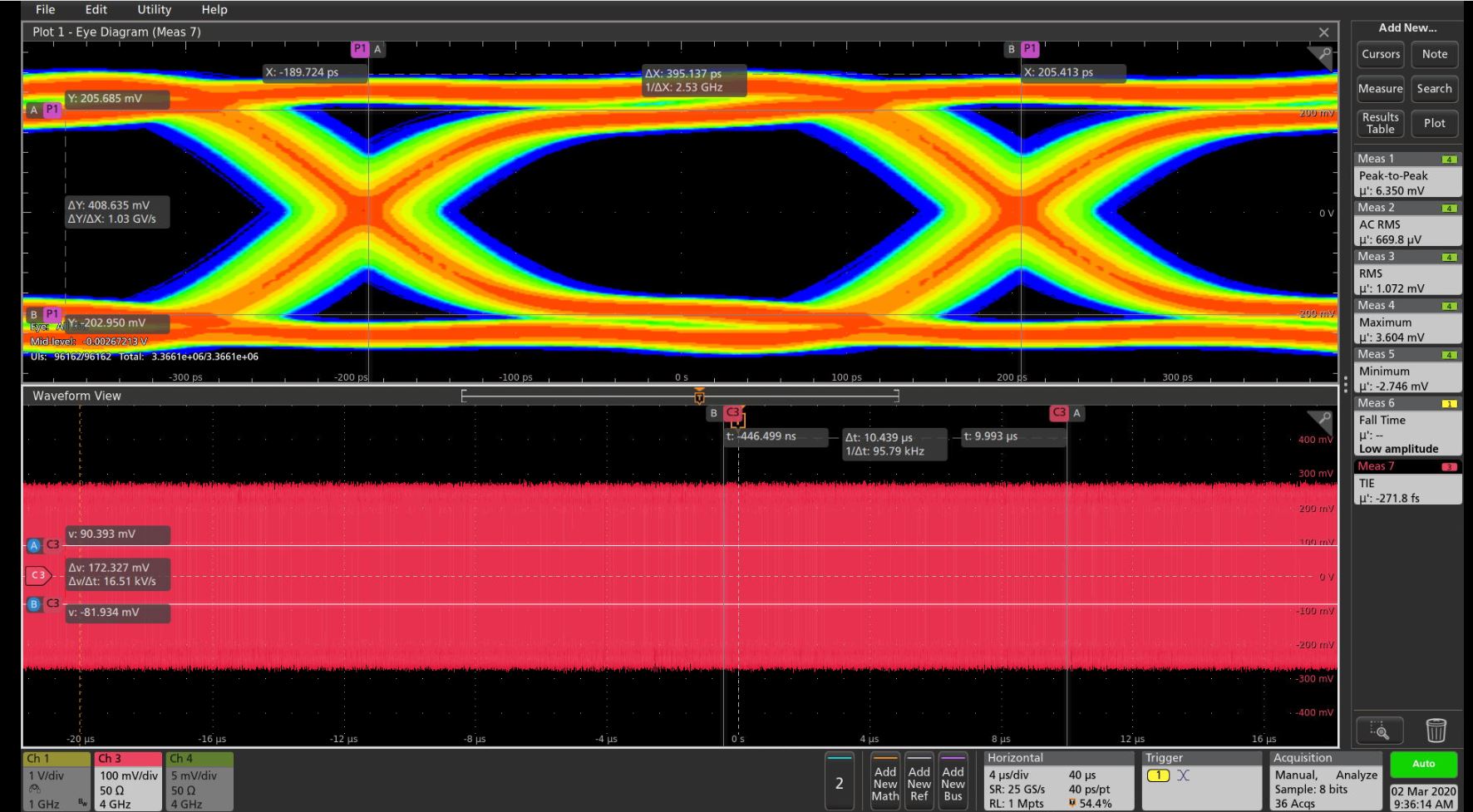
With a logic analyser, we can see that some i2c communications are taking much longer time and end up failing.
In this test, the backlight driver is writing a value to set the brightness.
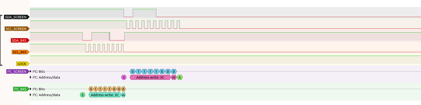
SDA_SCREEN & SCL_SCREEN are I2C communication on Deserialiser side
SDA_845 & SCL_845 are I2C communication on Serialiser side
The LOCK is also present
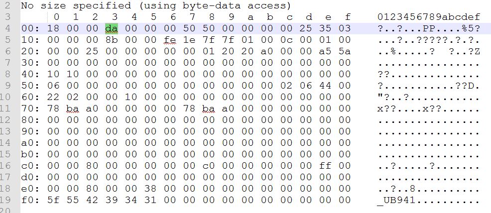
1st case : i2c write success
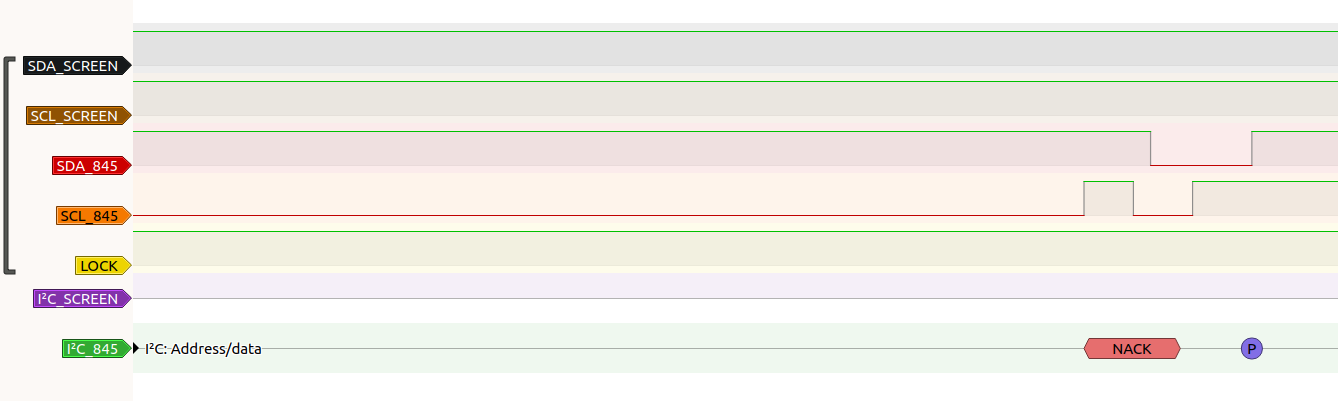
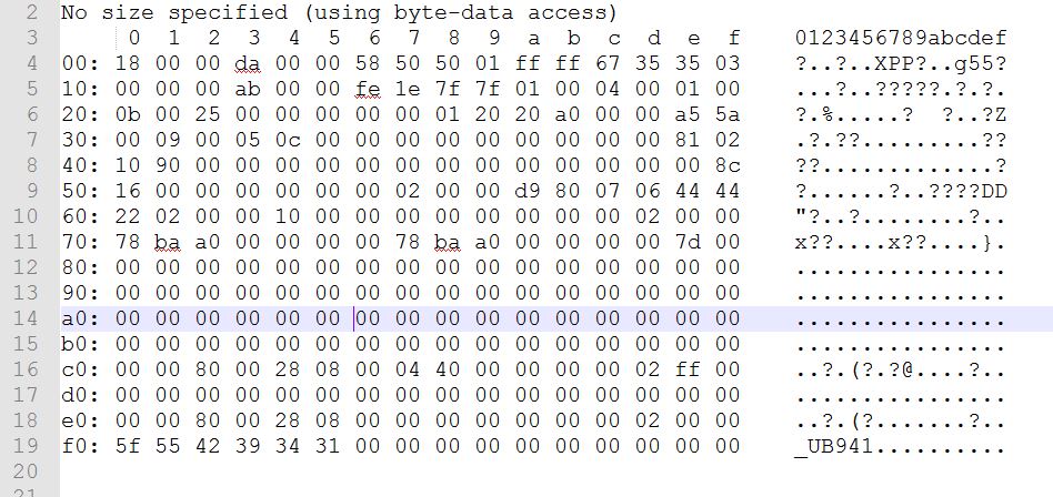
2nd case : i2c write error
We can see that ACK is never received on master side. After a while the master times out and stops the communication.
We can also see that the pin LOCK is still constant at that moment so that would mean that the serializer and deserializer are synchronized.
I2C clock frequency on SCREEN = 78 kHz
I2C clock frequency on 845 = 100 kHz
Is there a specific configuration of the SerDes register to improve the I2C communication ?
Thanks,
Best regards,
Alex