This thread has been locked.

If you have a related question, please click the "Ask a related question" button in the top right corner. The newly created question will be automatically linked to this question.

TPS65987D: TPS65987D HV_PP

Part Number: TPS65987D

Hello Support team,

My customer is evaluating TPS65987D on their board. When USB PD adapter is connected to their board, the VBUS voltage rise up to 20V, however, HV_PP switch never turn on. To turn on HV_PP, how  should they set TPS65987D?

They can't use GUI on their board.

Thanks,

Koji Ikeda

  • Hello Koji,

    Would you be able to share the project file they are using? Would like to see how they have the power paths configured in register 0x27. Are they using the SRDY command? If so, then the PD controller will not close the power path until it receives the 4cc command 'SRDY' from an I2C master. If the customer does not want this functionality, then have the power path they are using as sink only.

  • Adam-san,

    Thank you very much for your support.

    Unfortunately, they could not access to TPS65987D by TI GUI, they can see only information through MCU. Their register information on 0x27 is 0x0000000040000000. How they should change the setting on 0x27?

    Thanks,

    Koji Ikeda

  • Hello Koji-san,

    It seems that they are not programming the Internal switches.

    How is your customer programming the device? The TPS65987D operates by loading a firmware image from either an external SPI flash or an external EC through I2C commands. The following is a link for the configuration tool. At the bottom of the page is a series of video tutorials to help get started with the GUI.

    https://www.ti.com/tool/TPS6598X-CONFIG

    There are default templates within the configuration tool that your customer can use as a starting point.

  • Adam-san,

    They are programming through MCU. They have one question,

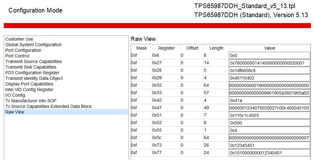
    E.g. on 0x28, GUI show 5 byte length, while application note shows 8 byte. Which is correct information? Does GUI skip "0"?

    And their register information are,

    ・Global System configuration (0x27): 0x0100020000008000141400000078

    ・TX Source Capa (0x32) :

    0x00000000000000000000000000000000000000000000000000000000000000000000000000000

    000000000000000000000000000000000000000000000000000

    ・TX Sink Capa (0x33):0x025a9001012c41060000000000008080808080808080808080808096b4888096b4888080808080808080808080808080808080808080800040

    ・Auto Negotiate (0x37)  : 0x2c4106008000

    ・PD3.0 configuration (0x42)  : 0x1a080000

    If you have any comment, please let me know.

    Thanks,

    Koji Ikeda

  • Adam-san,

    Could you support? Which is correct information for data length, application note or GUI?

    Thanks,

    Koji Ikeda

  • Hello Koji-san,

    Your customer needs to follow this app note if they are wanting to load a configuration using an external EC as opposed to a SPI flash. They must load the entire patch bundle before they write to specific registers within the device.

    https://www.ti.com/lit/an/slva972a/slva972a.pdf

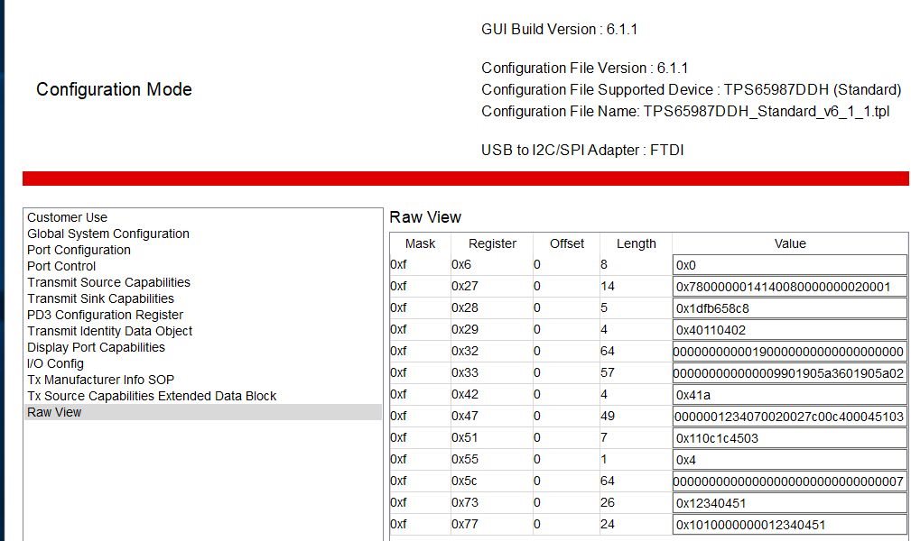
    Also, I recommend that you and your customer move to the latest configuration tool version. You are currently on v5.13 while the latest version should be v6.1.1

    https://www.ti.com/tool/TPS6598X-CONFIG 

  • Also, if you are wanting to do the patch bundle update through the PTCx commands, then you must use the advance template within the configuration tool, and update the I2C1 IRQ events as defined within the app note shared above.

  • Adam-san,

    Thank you for your support, however, this is not answer for their question. I confirm GUI v6.1.1, however, the word length on 0x28 shows 5, while application note show 8. Is this miss typo?

    Thanks,

    Koji Ikeda

  • Hello Koji-san,

    Yes that is a typo within the GUI. The application note is the correct byte length and description for that register.