This thread has been locked.

If you have a related question, please click the "Ask a related question" button in the top right corner. The newly created question will be automatically linked to this question.

TCAN4550EVM: How to connect and configure TCAN4550 EVM with MCU?

Part Number: TCAN4550EVM
Other Parts Discussed in Thread: MSP430FR6989, TCAN4550

Hi Team,

I would like test TCAN4550 CAN function, thus I would to use MSP430FR6989 to connect with it for testing.

I have 2 FR6989  + 2 TCAN4550 EVM.


The connection is shown below:

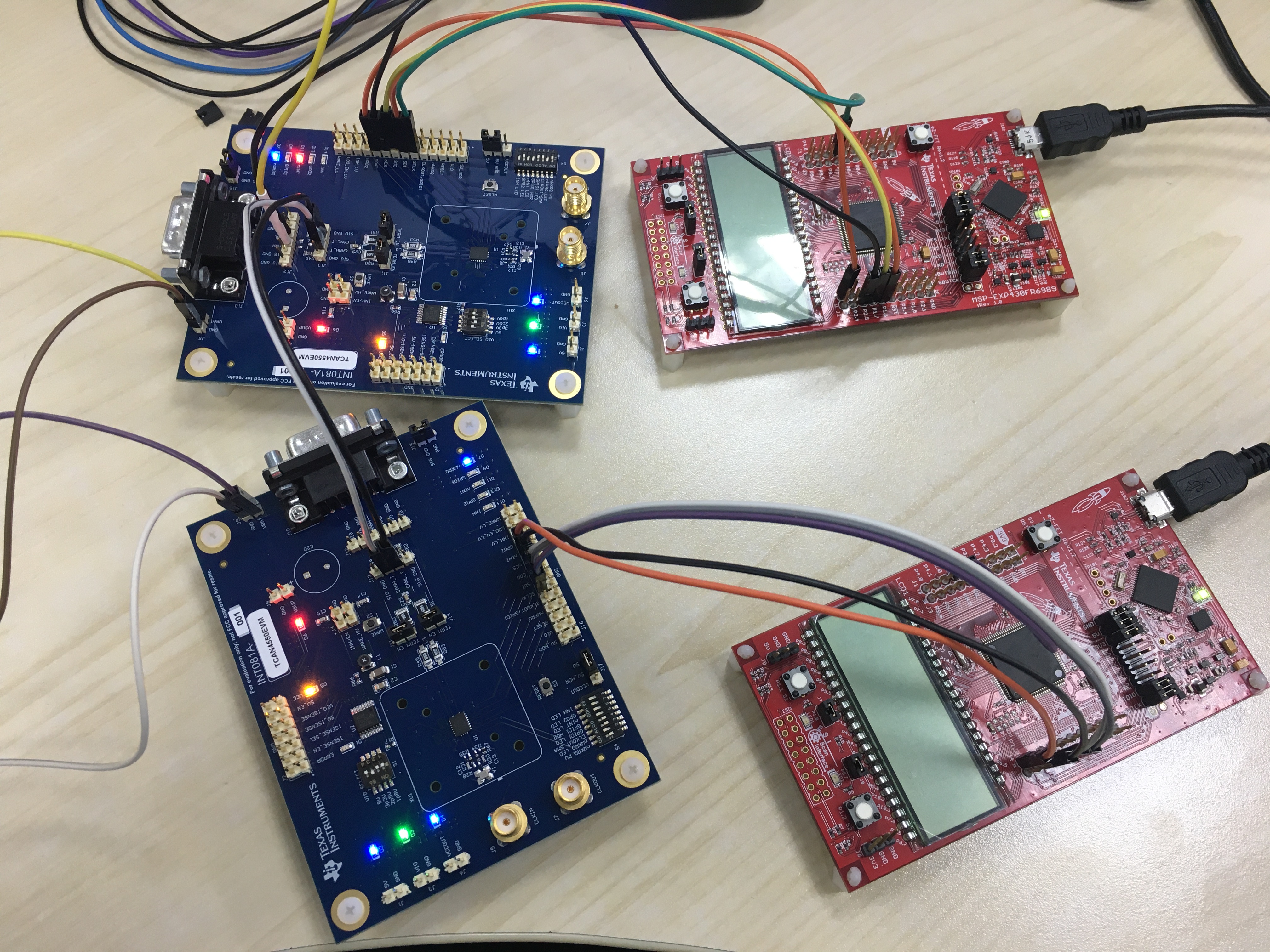
Power supply : DC - 12V

Demo: TCAN455x Driver Library Demo (Rev. A)

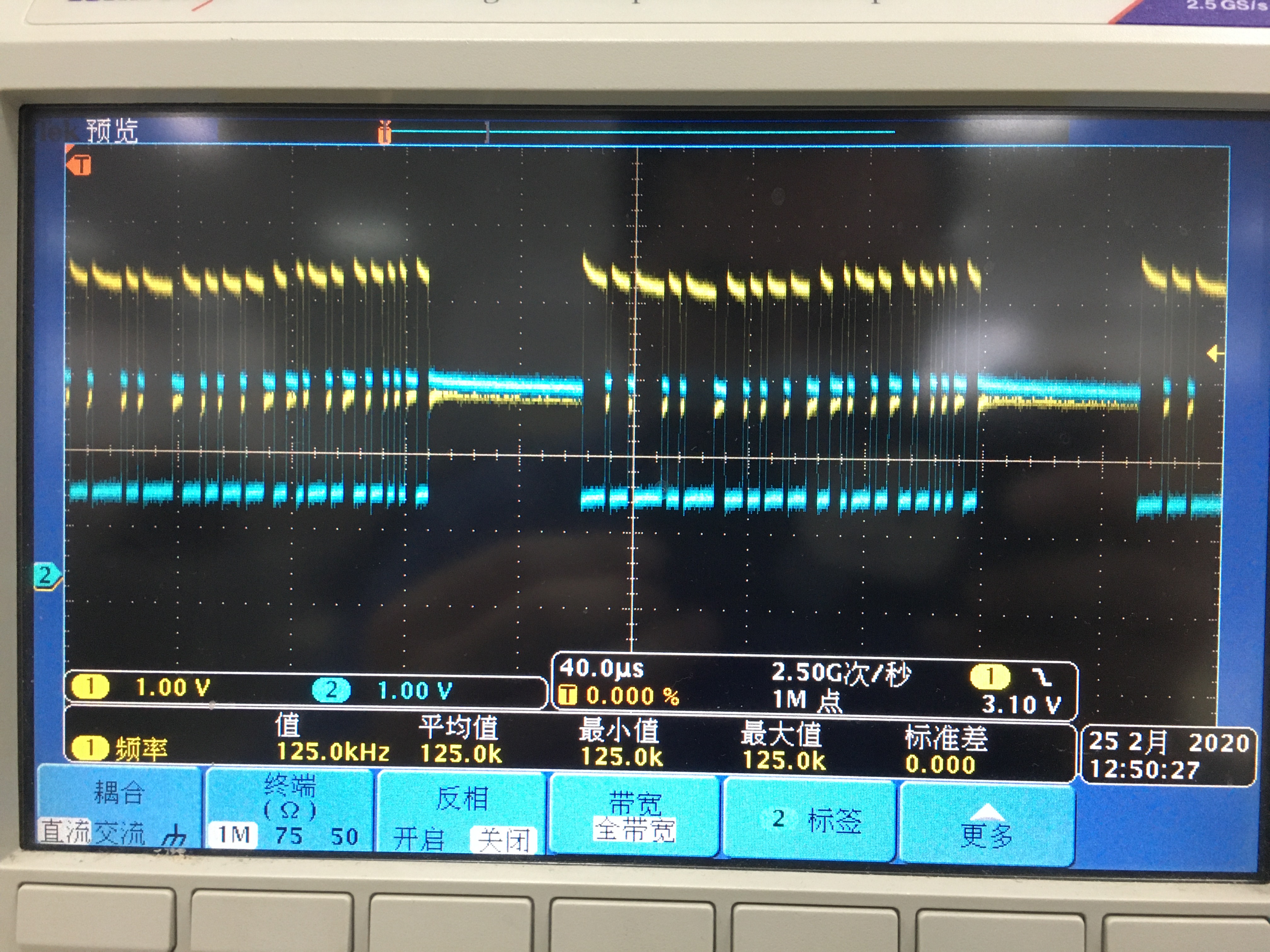
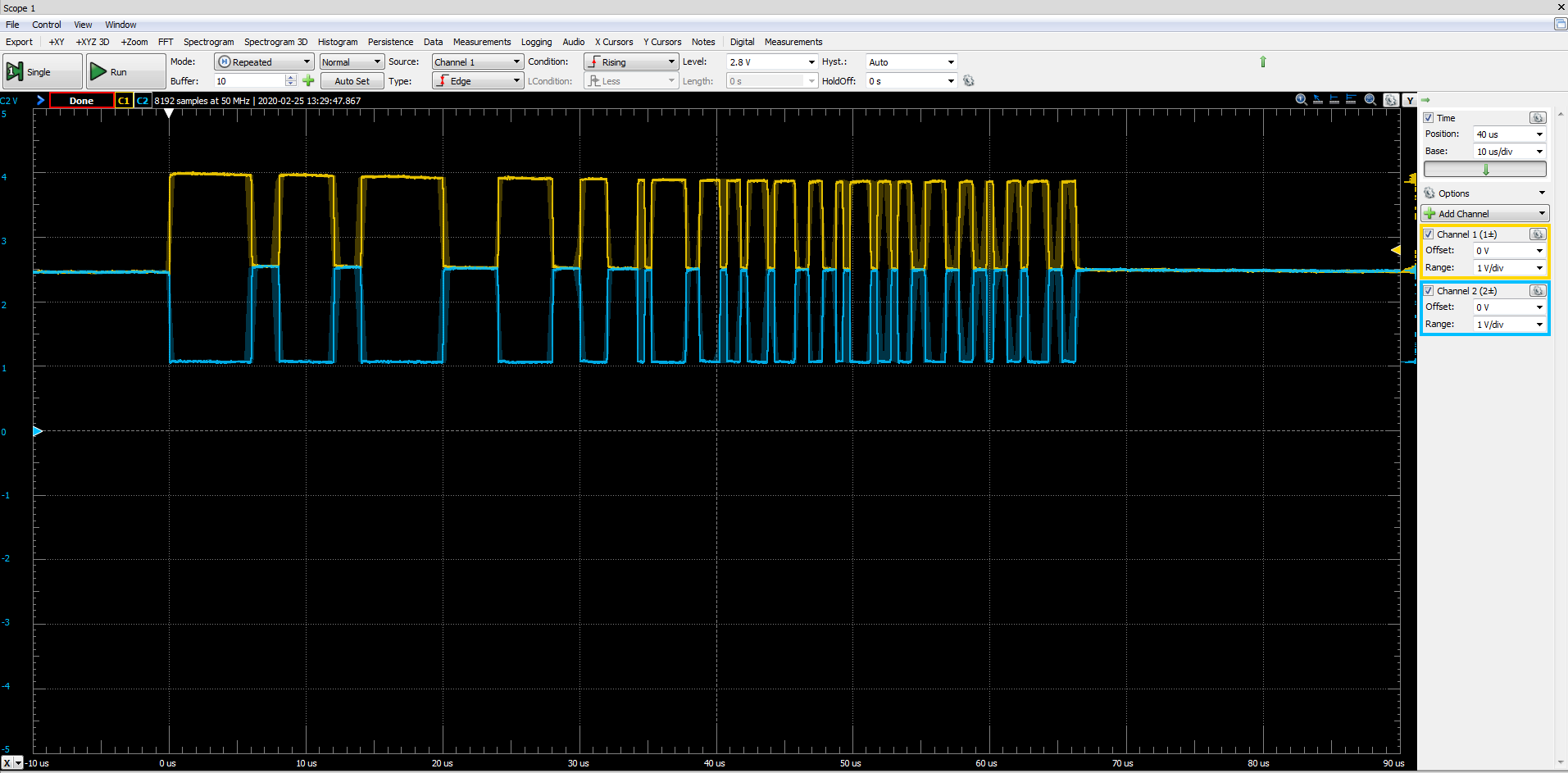
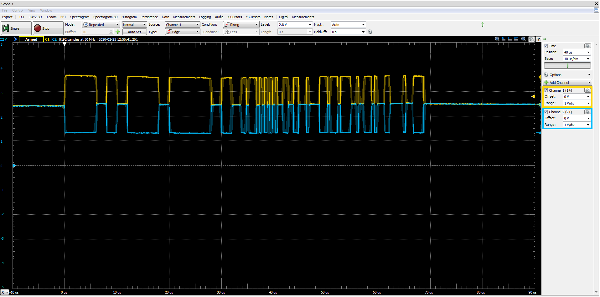
When pressing the S1 button (sending CAN data) at one MCU, the other MCU did not receive the corresponding interrupt, and I used a logic analyzer to monitor the CAN Bus waveform, and there was no waveform.

Where am I connected wrong on the hardware? Or do I need to make other settings?

Please help me.

Best Regards

Johnson

  • Hi Johnson,

    I don't see any ground connections between the TCAN4550 EVM's and the MSP430FR6989 LaunchPad boards.  In order for the SPI communication to be successful, you will need a good ground connection between the EVM and LauchPad.  Please connect an additional jumper wire between the EVM and the LauchPad for both sets and then try the communication again. You do not need to connect the grounds of the two TCAN4550 EVM's together, but each TCAN4550 EVM ground must be connected to the LaunchPad ground along with the SPI.

    I'm hoping the ground connections fix your problem, but if communication is still unsuccessful, then could you use your logic analyzer or scope to capture the SPI communication between the TCAN4550 and MCU's so that I can verify the SPI is functioning correctly?

    Regards,

    Jonathan

  • Hi Jonathan,

    This issue still exists after I connected the ground.

    I tried to read the Device ID register using SPI.

    The waveform is as follows. The result is "TCAN4550".

    According to the data provided by the datasheet, the SPI communication is normal.

    Do I need to set other switches on the board?


    I have observed that when I reset the TCAN4550 EVM (S3), D7 (nWKRQ) and D11 (nINT) will be on, and when I execute the CAN initialization code, D11 (nINT) will be off. These looks normal.

    Thus I think the SPI communication should be normal. The problem is that I can't capture the data on CAN Bus. It seems that the data is not sent by TCAN4550. Is there something wrong with my connection? Is it related to CAN configuration?

    CAN_INT demo as follow(I don't change anything with demo provide by TI):

    TCAN4x5x_Device_ClearSPIERR();         // Clear any SPI ERR flags that might be set as a result of our pin mux changing during MCU startup
    
    /* Step one attempt to clear all interrupts */
    TCAN4x5x_Device_Interrupt_Enable dev_ie = {0};		// Initialize to 0 to all bits are set to 0.
    TCAN4x5x_Device_ConfigureInterruptEnable(&dev_ie);      // Disable all non-MCAN related interrupts for simplicity
    
    TCAN4x5x_Device_Interrupts dev_ir = {0};		// Setup a new MCAN IR object for easy interrupt checking
    TCAN4x5x_Device_ReadInterrupts(&dev_ir);		// Request that the struct be updated with current DEVICE (not MCAN) interrupt values
    
    if (dev_ir.PWRON)                                       // If the Power On interrupt flag is set
      TCAN4x5x_Device_ClearInterrupts(&dev_ir);             // Clear it because if it's not cleared within ~4 minutes, it goes to sleep
      
    /* Configure the CAN bus speeds */
    TCAN4x5x_MCAN_Nominal_Timing_Simple TCANNomTiming = {0};	// 500k arbitration with a 40 MHz crystal ((40E6 / 2) / (32 + 8) = 500E3)
    TCANNomTiming.NominalBitRatePrescaler = 2;
    TCANNomTiming.NominalTqBeforeSamplePoint = 32;
    TCANNomTiming.NominalTqAfterSamplePoint = 8;
    
    TCAN4x5x_MCAN_Data_Timing_Simple TCANDataTiming = {0};		// 2 Mbps CAN FD with a 40 MHz crystal (40E6 / (15 + 5) = 2E6)
    TCANDataTiming.DataBitRatePrescaler = 1;
    TCANDataTiming.DataTqBeforeSamplePoint = 15;
    TCANDataTiming.DataTqAfterSamplePoint = 5;
    
    /* Configure the MCAN core settings */
    TCAN4x5x_MCAN_CCCR_Config cccrConfig = {0};					// Remember to initialize to 0, or you'll get random garbage!
    cccrConfig.FDOE = 1;										// CAN FD mode enable
    cccrConfig.BRSE = 1;										// CAN FD Bit rate switch enable
    
    /* Configure the default CAN packet filtering settings */
    TCAN4x5x_MCAN_Global_Filter_Configuration gfc = {0};
    gfc.RRFE = 1;                                               // Reject remote frames (TCAN4x5x doesn't support this)
    gfc.RRFS = 1;                                               // Reject remote frames (TCAN4x5x doesn't support this)
    gfc.ANFE = TCAN4x5x_GFC_ACCEPT_INTO_RXFIFO0;    // Default behavior if incoming message doesn't match a filter is to accept into RXFIO0 for 
                                                    //extended ID messages (29 bit IDs)
    gfc.ANFS = TCAN4x5x_GFC_ACCEPT_INTO_RXFIFO0;    // Default behavior if incoming message doesn't match a filter is to accept into RXFIO0 for 
                                                    //standard ID messages (11 bit IDs)
    
    /* ************************************************************************
    * In the next configuration block, we will set the MCAN core up to have:
    *   - 1 SID filter element
    *   - 1 XID Filter element
    *   - 5 RX FIFO 0 elements
    *   - RX FIFO 0 supports data payloads up to 64 bytes
    *   - RX FIFO 1 and RX Buffer will not have any elements, but we still set their data payload sizes, even though it's not required
    *   - No TX Event FIFOs
    *   - 2 Transmit buffers supporting up to 64 bytes of data payload
    */
    TCAN4x5x_MRAM_Config MRAMConfiguration = {0};
    MRAMConfiguration.SIDNumElements = 1;		// Standard ID number of elements, you MUST have a filter written to MRAM for each element defined
    MRAMConfiguration.XIDNumElements = 1;		// Extended ID number of elements, you MUST have a filter written to MRAM for each element defined
    MRAMConfiguration.Rx0NumElements = 5;						// RX0 Number of elements
    MRAMConfiguration.Rx0ElementSize = MRAM_64_Byte_Data;		// RX0 data payload size
    MRAMConfiguration.Rx1NumElements = 0;						// RX1 number of elements
    MRAMConfiguration.Rx1ElementSize = MRAM_64_Byte_Data;		// RX1 data payload size
    MRAMConfiguration.RxBufNumElements = 0;						// RX buffer number of elements
    MRAMConfiguration.RxBufElementSize = MRAM_64_Byte_Data;		// RX buffer data payload size
    MRAMConfiguration.TxEventFIFONumElements = 0;				// TX Event FIFO number of elements
    MRAMConfiguration.TxBufferNumElements = 2;					// TX buffer number of elements
    MRAMConfiguration.TxBufferElementSize = MRAM_64_Byte_Data;	// TX buffer data payload size
    
    
    /* Configure the MCAN core with the settings above, the changes in this block are write protected registers,      *
    * so it makes the most sense to do them all at once, so we only unlock and lock once                             */
    
    TCAN4x5x_MCAN_EnableProtectedRegisters();					// Start by making protected registers accessible
    TCAN4x5x_MCAN_ConfigureCCCRRegister(&cccrConfig);			// Enable FD mode and Bit rate switching
    TCAN4x5x_MCAN_ConfigureGlobalFilter(&gfc);                  // Configure the global filter configuration (Default CAN message behavior)
    TCAN4x5x_MCAN_ConfigureNominalTiming_Simple(&TCANNomTiming);// Setup nominal/arbitration bit timing
    TCAN4x5x_MCAN_ConfigureDataTiming_Simple(&TCANDataTiming);	// Setup CAN FD timing
    TCAN4x5x_MRAM_Clear();										// Clear all of MRAM (Writes 0's to all of it)
    TCAN4x5x_MRAM_Configure(&MRAMConfiguration);				// Set up the applicable registers related to MRAM configuration
    TCAN4x5x_MCAN_DisableProtectedRegisters();					// Disable protected write and take device out of INIT mode
    
    
    /* Set the interrupts we want to enable for MCAN */
    TCAN4x5x_MCAN_Interrupt_Enable mcan_ie = {0};				// Remember to initialize to 0, or you'll get random garbage!
    mcan_ie.RF0NE = 1;											// RX FIFO 0 new message interrupt enable
    
    TCAN4x5x_MCAN_ConfigureInterruptEnable(&mcan_ie);			// Enable the appropriate registers
    
    
    /* Setup filters, this filter will mark any message with ID 0x055 as a priority message */
    TCAN4x5x_MCAN_SID_Filter SID_ID = {0};
    SID_ID.SFT = TCAN4x5x_SID_SFT_CLASSIC;						// SFT: Standard filter type. Configured as a classic filter
    SID_ID.SFEC = TCAN4x5x_SID_SFEC_PRIORITYSTORERX0;	// Standard filter element configuration, store it in RX fifo 0 as a priority message
    SID_ID.SFID1 = 0x055;										// SFID1 (Classic mode Filter)
    SID_ID.SFID2 = 0x7FF;										// SFID2 (Classic mode Mask)
    TCAN4x5x_MCAN_WriteSIDFilter(0, &SID_ID);					// Write to the MRAM
    
    
    /* Store ID 0x12345678 as a priority message */
    TCAN4x5x_MCAN_XID_Filter XID_ID = {0};
    XID_ID.EFT = TCAN4x5x_XID_EFT_CLASSIC;                      // EFT
    XID_ID.EFEC = TCAN4x5x_XID_EFEC_PRIORITYSTORERX0;           // EFEC
    XID_ID.EFID1 = 0x12345678;                                  // EFID1 (Classic mode filter)
    XID_ID.EFID2 = 0x1FFFFFFF;                                  // EFID2 (Classic mode mask)
    TCAN4x5x_MCAN_WriteXIDFilter(0, &XID_ID);                   // Write to the MRAM
    
    /* Configure the TCAN4550 Non-CAN-related functions */
    TCAN4x5x_DEV_CONFIG devConfig = {0};                        // Remember to initialize to 0, or you'll get random garbage!
    devConfig.SWE_DIS = 0;                                      // Keep Sleep Wake Error Enabled (it's a disable bit, not an enable)
    devConfig.DEVICE_RESET = 0;                                 // Not requesting a software reset
    devConfig.WD_EN = 0;                                        // Watchdog disabled
    devConfig.nWKRQ_CONFIG = 0;                                 // Mirror INH function (default)
    devConfig.INH_DIS = 0;                                      // INH enabled (default)
    devConfig.GPIO1_GPO_CONFIG = TCAN4x5x_DEV_CONFIG_GPO1_MCAN_INT1;    // MCAN nINT 1 (default)
    devConfig.FAIL_SAFE_EN = 0;                                 // Failsafe disabled (default)
    devConfig.GPIO1_CONFIG = TCAN4x5x_DEV_CONFIG_GPIO1_CONFIG_GPO;      // GPIO set as GPO (Default)
    devConfig.WD_ACTION = TCAN4x5x_DEV_CONFIG_WDT_ACTION_nINT;  // Watchdog set an interrupt (default)
    devConfig.WD_BIT_RESET = 0;                                 // Don't reset the watchdog
    devConfig.nWKRQ_VOLTAGE = 0;                                // Set nWKRQ to internal voltage rail (default)
    devConfig.GPO2_CONFIG = TCAN4x5x_DEV_CONFIG_GPO2_NO_ACTION; // GPO2 has no behavior (default)
    devConfig.CLK_REF = 1;                                      // Input crystal is a 40 MHz crystal (default)
    devConfig.WAKE_CONFIG = TCAN4x5x_DEV_CONFIG_WAKE_BOTH_EDGES;// Wake pin can be triggered by either edge (default)
    TCAN4x5x_Device_Configure(&devConfig);                      // Configure the device with the above configuration
    TCAN4x5x_Device_SetMode(TCAN4x5x_DEVICE_MODE_NORMAL);       // Set to normal mode, since configuration is done. This line turns on the transceiver
    
    TCAN4x5x_MCAN_ClearInterruptsAll();                         // Resets all MCAN interrupts (does NOT include any SPIERR interrupts)

    Best Regards

    Johnson

  • Hi Jonathan,

    Some update about this issue :

    I used the oscilloscope to capture the CAN bus waveform and found that:

    When Lanuchpad S1 is pressed (execute TCAN4x5x_MCAN_TransmitBufferContents (0);),

    the CAN bus has been sending data and will not stop. But the other end was not interrupted.


    Therefore, I am more confused:

    Why is there always a waveform of data transmission on the CAN bus although one transmission is finished?
    Secondly, there are waveforms on the CAN bus, but I cannot receive interrupts. Is this related to the CAD ID or filter?

    Could you help test this demo using FR6989 in your side? 

    Best Regards

    Jonson

  • Hi Jonson,

    First I'll explain the repeated transmission of the message you observing.  When the controller sends a message on the CAN bus, it expects to receive an acknowledge (ACK) from another node on the bus.  If it does not receive an ACK, it will determine the message transmission was unsuccessful and it will try to send the message again until it receives an ACK.  If one of your nodes has a problem receiving a message, it will not acknowledge the reception of an error free message and therefore the original node will continuously send the message until it receives an ACK.  This is what you are observing because each press of the button should only result in a single message being transmitted and acknowledged by the other node.

    Thank you for verifying the SPI communication is good.  I believe we can eliminate the EVM to MCU connection as the cause of the problem.  However I did look at your setup picture again based upon the new information and the repeated messages.  I found one additional adjustment that I recommend you make.  I see that you are using the pins labeled "CANH_T" and "CANL_T" of Header J13 for your CAN bus wires between the boards.  I recommend you use the "CANH" and "CANL" pins of Header J12 instead.  The pins you are currently using were intended as injection points for transient signals such as noise, glitches, offset voltages, etc. and have a 330 ohm resistor between the pin and the CAN bus.  Since you are are using the same header on both boards, you have added 660 ohms series resistor on each of the CANH and CANL signals between the two TCAN4550 transceivers.  The signal amplitude of your scope signals look large enough to achieve proper communication, but just to be sure, please move the wires to J12 to be sure this isn't the cause of the communication error.

    My second observation is that your CAN waveform does not look correct to me for what I expect from the demo software.  I didn't see if your message ID and data payload was the same as mine because that portion of code is below the portion of the code you shared.  The demo code sends a packet with ID 0x144 and data 0x55, 0x66, 0x77, and 0x88 when it first starts up.  Then the code changes the buffer data to an ID of 0x123 with data 0x11, 0x22, 0x33, and 0x44 to be sent when the S1 button is pressed.  Unless the code is modified, I expect you should be observing one or the other of these messages.

    This is the waveform I expect to see from the first message with ID 0x144:

    This is the waveform I expect to see from the first message with ID 0x123:

    Observations I made on your scope waveform:

    1.) The time scale appears off.  If I am reading your scope correctly, it is set for 40uS per division.  If so, your entire message appears to take about 140uS.  Using the default bit timing settings on my setup, I see the message transmitted in about 66uS.  The demo code assumes a 40Mhz clock frequency, and the EVM should have a 40Mhz crystal installed on the board by default.  The code also sets the Arbitration bit rate at 500kbps and a data rate of 2Mbps.  So either the code settings are set different, or there is a problem with the crystal oscillators making the timing settings different.  If only one board has a problem, the other board won't acknowledge the message.

    2.) The message ID does not appear to match the expected value of either of the default messages in the demo code.  There are too many bit transitions in your messages and the Arbitration phase and the Data phase of the message appear to be set at the same frequency and not the 500kbps/2Mbps default values. 

    Can you please try to measure the crystal/clock frequency on both boards, and also check the message ID and data buffer values?  There should not be any filtering applied and any valid message should be acknowledged, but if you are tying to transmit the same message as I am, the waveforms clearly don't match mine.

    Can you try powering up the boards by themselves and monitor the waveforms each board is producing.  Are they the same?  Then power on the other board and see if there are any clues to which board has a problem.  This would help point to a specific board with a hardware problem, or corrupted code, etc.  If both boards appear the same, then we need to look at all of the code again.

    Can you also try to set some breakpoints in the code and monitor the TX and RX buffer contents to see if they are as expected?  The RX of one board should match the TX of the other board. 

    Hopefully something in this message will fix the problem or help us figure this out.  Once you have tried these things, let me know what you found out.

    Regards,

    Jonathan

  • Hi Jonathan,

    The problem is found.

    When I use two FR6989 + TCAN4550 for CAN communication, the filter ID setting needs to correspond to the CAD ID sent by the other party.

    Now my setting as follows:

    Board1: CAN_ID : 0x123      SFID: 0x124
    Board2: CAN_ID : 0X124     SFID: 0x123

    And the test results show normal.


    thank you for your help.

    Best Regards

    Johnson