This thread has been locked.

If you have a related question, please click the "Ask a related question" button in the top right corner. The newly created question will be automatically linked to this question.

THVD1450: THVD1450 possible latch up (chip burnt)

Part Number: THVD1450

Hello

We have a designed and tested a few boards with THVD1450. The boards work well, but every now and then at power up, we see the THVD1450 chip on the board get hot and sometimes even burn out. Attached is a picture. IC4 is THVD1450. Pin A was shorted to ground. all regulators on board worked fine. When the part was desoldered the short went away. 

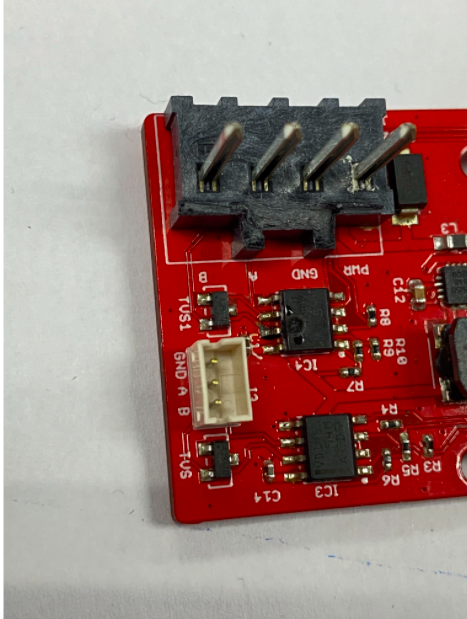
After some debug on the board, we felt that its an issue with just the THVD1450 - a possible latch up issue because it happens only during the first few minutes of start up. After digging through the data sheet, I noticed the following. 

Page 29 of the datasheet, layout guidelines #7, which mentions the following

"Insert pulse-proof resistors into the A and B bus lines if the TVS clamping voltage is higher than the specified maximum voltage of the transceiver bus pins. These resistors limit the residual clamping current into the transceiver and prevent it from latching up."

Figure 37 on the datsheet also shows these pulse proof resistors that we have not placed in our design. I have the SM712 ESD part which gives a clamping voltage of ~19 for a 1A current. 

In light of this we are going to change the design to place these resistors, but I wanted to do a quick check in with the experts at TI to make sure that this issue of THVD1450 burn up is indeed a latch up issue because of the lack of pulse proof resistor or could it be sign of something else? I'm guessing the application engineers at TI must have seen similar issues like this? 

Thanks

Raghu

  • Hi Raghu,

    Is that photo showing that the plastic packaging has even melted a little bit in the vicinity of pin 7?  The only things I can think of that would result in that level of heating would be latch-up (as you mentioned) or some other extreme stress applied at the bus pins (such as a short-circuit to a high DC supply or large transient voltage/current spike).

    We don't have any known issues related to latch-up on this device.  It was tested for latch-up immunity prior to production and anecdotally I'd say a large portion of current applications for it do not use series current-limiting resistances on the bus lines.  So, while we shouldn't rule that out as a root cause I would like to better understand the usage in this application to see if it creates any atypical stresses.

    How many units failed, and how many were tested?

    Is anything connected to the A/B lines at power-up or at any point prior to the failure, or are they left floating as shown in your photo?  If something is connected to them, would it be possible to monitor their voltages on an oscilloscope to make sure everything remains within expected ranges?  (The SM712 should be helping to enforce this, but I'd still like to check.)

    Have you observed the VCC ramp-up on an oscilloscope to verify that it reaches the target level with no significant overshoots?

    I'm assuming C1/C14 are the decoupling capacitances - what is their value?

    Regards,
    Max

  • Hi Raghu,

    Did you find any resolution to this issue?  If not, are you able to review my questions above?

    Thank you,
    Max

  • Hi Max 

    Sorry for such a late reply. The notifications for this thread went to my spam and I got so busy with other stuff that I forgot about this question. Apologies.

     We have sent our new design for fabrication and assembly. I will notify you of the results. But I would also like to answer your questions. 

    1. How many units failed, and how many were tested? - We have about 30 boards. Out of this two failed and burnt but other have experienced the issue where the chip heats up during start up but they don't burn

    2. Is anything connected to the A/B lines at power-up or at any point prior to the failure, or are they left floating as shown in your photo? - A/B lines were left floating during start up. 

    3. Have you observed the VCC ramp-up on an oscilloscope to verify that it reaches the target level with no significant overshoots?- We have not done this for overshoots. I will look into this. 

    4. I'm assuming C1/C14 are the decoupling capacitances - what is their value?- Yes. they are both 100nF 

    Thanks

    Raghu

  • Raghu,

    Thanks for the update.  This is a really puzzling issue, since nothing you are describing sounds like an undue stress to the part.  I would definitely check the VCC waveform with respect to IC GND next just to make sure it is at the target level and that overshoots or ripple do not result in absolute maximum ratings violations.

    Max

  • Hi Max

    So we checked the Vcc rail and there does not appear to be any overshoot on the 5V rail for all of our 3 designs. This is during start up when we have seen the assumed "latch up" problem. 

    I will update on the testing with the new boards as soon as we get those board back from assembly.

    Thanks

    Raghu