This thread has been locked.

If you have a related question, please click the "Ask a related question" button in the top right corner. The newly created question will be automatically linked to this question.

DS90UB935-Q1: Do I need to design a re-driver( repeater) for extend the coaxial cable connection between 935 and 936?

Part Number: DS90UB935-Q1

Hi,

As I know FPD-Link III supports 15m cable length, but what should i do if my client need it to be support 30m length coaxial cable?

Design a repeater?or use adaptive cable equalizer?

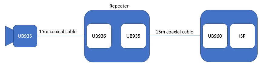
here is my idea for designing the repeater.
  • Hello Joanathan,

    To support 30m a repeater would be the recommended method and it can be implemented as per your picture. 

    Best Regards,

    Casey 

  • Hi Casey,

    Thanks for reply.

    In this connection as previous picture, how should I config the I2C address ( IDX pin) or Device ID( Register setting) on each 935, 936 and 960?

    If the same camera module connects to other port of 960 w/o repeater, do i have to modify the I2C address ( IDX pin) or Device ID( Register setting) on 935 and 960?

  • Jonathan,

    Below are some things to pay attention to when setting up a repeater. All I2C communication should pass through just fine however it is vital that each device on the bus be properly aliased. This is so the I2C can be encoded and sent through the FPD-Link cable and end up on the correct bus. Below there is a step-by-step documentation of how each register should be set up to send I2C data through the repeater. After all devices have been aliased, you can communicate via I2C using just the alias addresses. Also a similar question was asked previously that may have some more information that could help. And lastly I included a quick demo script that should show how the I2C id and I2C alias registers should be set.

    Registers to set for 960

    • ISP sends I2C to 960
    • 0x5B (SER_ID) should be set to the i2c address of the 935. (should populate automatically)
    • 0x5C (SER_ALIAS_ID) needs to be set to a unique value i.e. 0x1C.
    • 0x5D (SlaveID[0]) should be set to match the address of the 936.
    • 0x65 (SlaveAlias[0]) should be set to a unique value i.e. 0x66.
    • 0x5E (SlaveID[1]) should be set to match the aliased address of second 935. (0x36)
    • 0x66 (SlaveAlias[1]) should be set to a unique value i.e. 0x42.
    • 0x5F (SlaveID[2]) should be set to match the aliased address of the sensor. (0x38)
    • 0x67 (SlaveAlias[2]) should be set to a unique value i.e. 0x40.

    Registers to set for 936

    • 0x5B (SER_ID) should be set to match id of 935 (should populate automatically)
    • 0x5C (SER_ALIAS_ID) should be set to a unique value i.e.0x36
    • 0x5D (SlaveID[0]) should be set to the real ID of the sensor.
    • 0x65 (SlaveAlias[0]) should be set to a unique value i.e.0x38


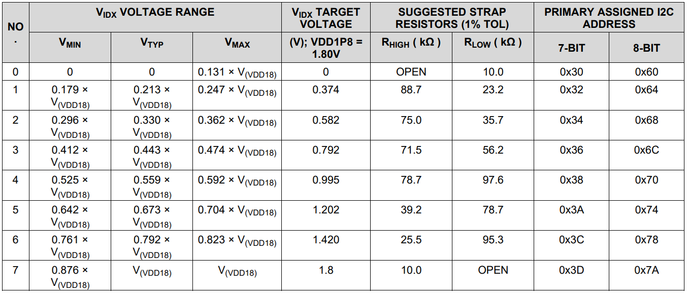
    The IDX pin can be set via the tables below for the 960, 935, and 936 respectively. However as long as the devices are aliased correctly it should work unless there will be many other devices on any of the I2C buses.

    Also I have included a simple script that shows how to alias everything in your diagram, I hope it is helpful.

    And finally, for some additional information, a similar question was asked before and a link to that thread can be found here: https://e2e.ti.com/support/interface/f/138/t/870119

    Regards,

    Nick


    IDX Values for 960

    IDX Values for 935

    IDX Values for 936

    Example script for setting Alias registers

    board.WriteI2C(0x7A, 0x4C, 0x0F) # Turn on FPD Link ports for writing
    board.WriteI2C(0x7a, 0x5B, 0x30) # Writing Serializer real ID to UB960
    board.WriteI2C(0x7a, 0x5C, 0x1C) # Settinf 935 Serializer Alias to 1C
    
    print('remote serializer: ' + hex(board.ReadI2C(0x1C, 0x00)))
    
    board.WriteI2C(0x7a, 0x5D, 0x60) # Writing remote slave device(UB936) real ID
    board.WriteI2C(0x7a, 0x65, 0x66) # Creating Alias for remote slave device(UB936)
    
    print('remote deserializer: ' + hex(board.ReadI2C(0x66, 0x00)))
    
    board.WriteI2C(0x66, 0x4C, 0xFF) # Turn on FPD Link ports for writing
    board.WriteI2C(0x66, 0x5B, 0x30) # Writing second remote serializer real ID(UB935) to remote deserializer(UB936)
    board.WriteI2C(0x66, 0x5C, 0x36) # Creating alias for second remote serializer(UB935)
    
    print(hex(board.ReadI2C(0x66, 0x5C)))
    
    board.WriteI2C(0x7a, 0x5E, 0x36) # Writing real ID for second serializer(UB935) that is aliased by UB936
    board.WriteI2C(0x7a, 0x66, 0x36) # Creating alias for second remote serializer(UB935)
    print(hex(board.ReadI2C(0x7a, 0x66)))
    print('second remote serializer: ' + hex(board.ReadI2C(0x36, 0x00)))
    
    #board.WriteI2C(0x66, 0x5D, *0x00*) # Starred value should be the value of the sensor connected to second remote serializer
    board.WriteI2C(0x66, 0x5D, 0x00) # 0x00 is a placeholder for this address
    board.WriteI2C(0x66, 0x65, 0x38) # Creating alias for sensor in remote deserializer(UB936)
    
    board.WriteI2C(0x7a, 0x5F, 0x40) # Writing real ID for sensor that is aliased by UB936
    board.WriteI2C(0x7a, 0x67, 0x40) # Creating alias for sensor for UB960