This thread has been locked.

If you have a related question, please click the "Ask a related question" button in the top right corner. The newly created question will be automatically linked to this question.

TVS1400: placement of TVS

Part Number: TVS1400
Other Parts Discussed in Thread: TPD2E007

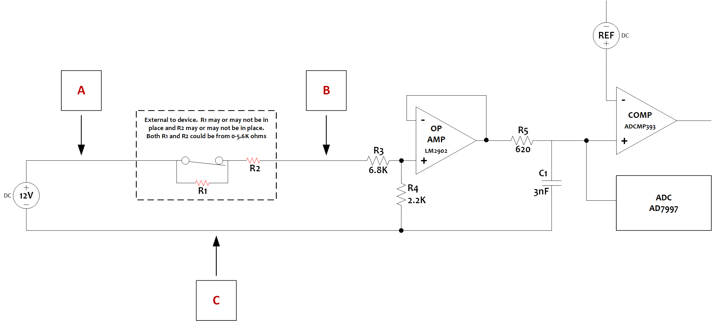
I am working on a design that includes the circuit as shown in the schematic here and am seeking guidance on both the choice and placement of TVS ICs which may include the TVS1400.  The device includes a 12V rail which supplies 12V to 32 of these circuits, for simplicity i've only shown one here.  I am interested in protecting the device from ESD and lightning but am not clear on where I should place TVS and which TVS to utilize.

If I understand things correctly

1. an ESD/lightning event occurring at A will flow towards the 12V source, here that would be from left to right, because that is path of least impedence.

2. an ESD/lightning event occurring at B will flow toward the op-amp only if R1+R2 > 9K ohms otherwise it will flow toward the 12V source

If I am correct above then I should place a TVS device at both A & B correct?  Is there any need to place a TVS device at C?

  • Hi Sean,

    From your design I can see that, correct me if I'm wrong, you have a switch that will sometimes be open. In that case if you would like to protect both the downstream circuitry and the power source then I would suggest placing a TVS1400 at both A and B. Since C is at ground there is no need to add a TVS in this case.

    For the suggestion portion you have already chosen the best TVS that we have in our portfolio for your application.

    So just a follow up question let me know if my understanding of the switch is correct and if you have any other question.

    Regards,

    Andy Robles

  • Hi Andy,

    You're understanding is correct, the switch will at times be open and at other times be closed.  In some cases R1 will be there and other cases it will not.

    I have a version of my design that utilizes TPD2E007 in position B, I chose this because I could terminate 2 circuits to each TPD2E007.  I will add a TVS1400 for position A.  Are there reasons I should replace the TPD2E007 with the TVS1400?   The TVS1400 has 3 IN pins, my understanding is that all 3 must be connected to the same circuit and it is not possible to use each for a different circuit correct?  If the TPD2E007 is not the correct choice for position B and the TVS1400 is a single circuit device is there an option that would support at least 2 circuits?

    thx - sean

  • Hi Sean,

    You are correct about the configuration of the TVS1400. All 3 pins must be connected to the same circuit. 

    The TPD2E007 is also one of our transient voltage suppressor devices, and it seems it can be used for your application. The advantage is that you'll be able to connect 2 circuits to each device reducing your bill of materials. One thing I saw in the datasheet I'd like to point out is that the max surge current for each device is different. The TVS1400 can handle a maximum surge current of 43A while the TPD2E007 can only handle up to 4.5A. On the other hand, the TPD2E007 can handle higher voltage discharges than the TVS1400.

    From my point of view, both of these devices are acceptable for your application. I do recommend going over the datasheet for both and ensure that both devices provide the level of protection you're trying to achieve.

    Let me know if you have any other questions!

    Regards,

    Andy Robles

  • Thanks Andy.

    Thanks for confirming the TVS1400 as a single channel device.

    For clarity I'm not an EE; my expertise is in networking, OS, databases and applications (things logically above the HW design) so I'm a bit out of my depth and am looking to the expertise of others to help sort out the few details I've not been able to fully resolve myself one of which is protecting my device from electrostatic discharge and lightning.  Will both the TVS1400 and the TPD2E007 provide protection from these?  If it is possible to use either for this then I'll place a TVS1400 in position A and place 16 TPD2E007 in position B with each serving two channels otherwise I'll place 32 TVS1400 in position B with each serving one channel.

    thx - sean

  • Hi Sean,

    So as clarification the TVS1400 is better than the TPD2E007 for surge events such as lightning and ESD. In which case I would suggest using the TVS1400 instead of the TPD2E007 where it's necessary.

    Now do have a follow up question to find out if you need 1 TVS1400 at point B or 32.

    1. Is there only going to be one switch or a switch for each one of the circuits shown in the schematic?

    2. If there's only 1 switch will the 12V rail after the switch split up to the 32 circuits in the complete schematic?

    If this is the case then you would only need 1 TVS right after the switch. That one TVS will protect all the op amps and any other downstream circuitry.

    Regards,

    Andy Robles

  • Thanks Andy.

    There are 32 circuits external to the device, all 32 are run off a common 12V.  Each circuit includes the R3/R4 voltage divider and terminates to the quad op-amp (TI LM2902DR) with each op-amp hosting 4 circuits.  The 4 circuits hosted on the op-amp are connected to a quad comparator and the set of circuits hosted by a pair of op-amp/comparators are hosted on an 8 channel ADC.

    External to our device each of these circuits could host one to five switches.

    I suspect the answer is I need 32 of the TVS1400 but if you e-mail me at sean.maddox@qastle.io I can send you the full schematic if that makes things easier.

    thx - sean

  • Hi Sean,

    I sent you an email so we can continue this conversation. Let me know if you didn't receive it.

    Regards,

    Andy Robles