Part Number: ONET1151L
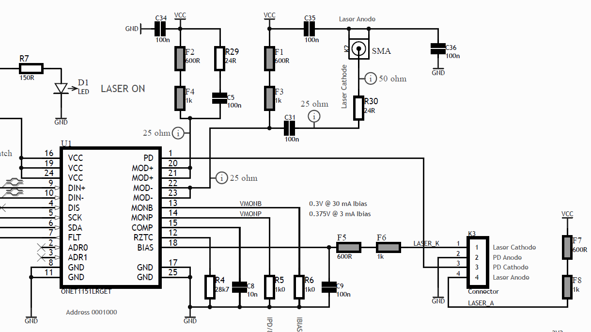
I've designed a circuit around the ONET 1151L to drive a laser diode with 1-2 Gbps signals. We have been trying in open loop so far, setting the bias and modulation current. When setting different bias currents with no modulation and measuring power we get the P-I graph matching the datasheet. But when adding modulation current (PRBS signal DC balanced) the resulting power is not the expected (corresponding to IBIAS + 1/2 IMOD) but much less. A practical example:
We set Ibias = 20 mA (right above the laser knee) and Imod = 0. Optical power is P1
We set Ibias = 20 mA and Imod = 20 mA, we measure optical power P2.
We set I bias = 20 + 0.5 * 20 = 30 mA. We measure optical power P3.
We expect P2 being equal to P3, but what we observe is P2 just slightly above P1.
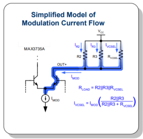
I assumed modulation current is on top of bias current, even if the laser is AC-coupled, because the driver only sinks current. From results it looks like modulation current is AC added to bias. Even though, the AC amplitude is less than expected
Looking at the waveform from the detector, it is well shaped up to 2 GHz, but again the AC amplitude doesn't show the same gain, for example, with Imod = Ibias, we observe a DC voltage and an AC voltage less than the DC, while we expected the same.
I'm aware the rest of circuitry may affect the results I'm getting but I'd appreciate any pointers about potential reasons and ways of further testing