This thread has been locked.

If you have a related question, please click the "Ask a related question" button in the top right corner. The newly created question will be automatically linked to this question.

DS90UB913A-Q1: Configure a DIN pin as general purpose input in DS90UB913A Serializer and have it send data to DS90UB936 DeSerializer

Part Number: DS90UB913A-Q1

Hi TI Team,

We are using DS90UB913A serializer with DS90UB936 deserializer. Both are being used in RAW10 mode. 

We want to transfer the status of a switch placed on the Serializer side to the Deserializer and then to Processor. DS90UB913 Serializer datasheet states that it has only GPO's and no GPIO's are available. Hence, no GPO's can be configured as inputs to transmit switch status. 

Question-1

---------------

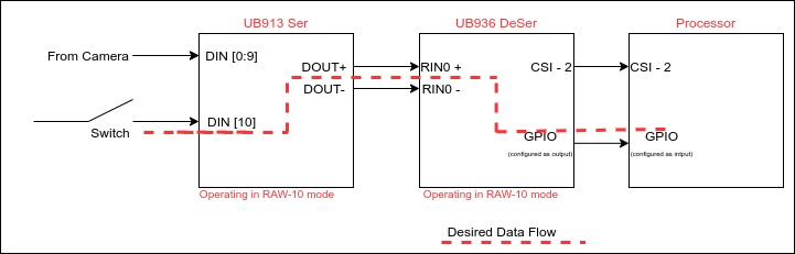
Since we are operating the ser-deser pair in RAW-10 mode, we have DIN-10 and DIN-11 data inputs not connected. Can we use DIN-10/DIN-11 (of the serializer) as general purpose input to transmit the switch status?

Below is the complete data flow we are expecting acheive:

Switch Status -> Serializer DIN-10/DIN-11 -> Serializer DOUT -> DeSerializer RIN0 -> DeSerializer GPIO (o/p) -> SOC GPIO (i/p)

Question-2

--------------

If it is not possible to achieve the above mentioned data flow, is there any other way we can transmit status of a switch placed on the serializer side (i.e. can a pin on the serializer be configured as an input) ?

Regards,

Khilav

  • Hello Khilav,

    Yes this is possible. Just make sure to set the device in RAW12 mode so that the DIN10-DIN11 are active. 

    Best Regards,

    Casey 

  • Hi Casey,

    Thank you very much for the confirmation.

    1.) Could you please let me know what other register changes shall I do in the ser-deser pair for enabling this ? (other than enabling RAW12 mode in Reg 0x6D[0:1])

    2.) How do I bifurcate the "video data" from "switch status data" on the deserializer side ?

    3.) How do I transfer the "switch status data" available on RIN0 port of the deserializer, to its GPIO ?

    Regards,

    Khilav

  • Hello Khilav,

    My apologies, when I looked at your original question I thought you were using DS90UB913 to DS90UB914. If you are using 936 there is no way to send this signal to a GPIO pin. The only way to send this signal back would be through I2C where a master at the 913 side writes to the GPIO control registers of the 936 through the bidirectional control channel or if the master at the 936 side reads some status back from a device attached to 913 and then toggles the GPIO accordingly. 

    Best Regards,

    Casey 

  • Hi Casey,

    There is a tad bit of confusion. You mentioned:

    "or if the master at the 936 side reads some status back from a device attached to 913 and then toggles the GPIO accordingly."

    How exactly do I read the status of something connected on 913 Ser (913 Ser only has GPOs) from 936 DeSer? In my case the Processor (Master) is attached to the 936 DeSer while an MCU GPIO & Camera Sensor are connected to the 913 Ser.

    I want to read the status of the MCU pin attached to 913 Ser. Where shall i connect this MCU pin on the 913 Ser and how shall I read its status on 936 DeSer?

    NOTE: The switch in the original question's block diagram is actually MCU's GPIO pin. I just mentioned it as a switch to make things easier.

    Regards,

    Khilav Soni  

  • Hello Khilav,

    The 936 can access remote slaves connected to the 913's I2C bus through the bidirectional control channel. Any devices attached to the 913's I2C bus are considered slaves. If the MCU on the 913 side can be accessed as a slave device then the 936 can read a register or status from the MCU as long as it knows the MCU's I2C address. Alternatively if the MCU on the 913 side is a master, then the MCU can write the deserializer's GPIO control registers through the bidirectional control channel to toggle a GPIO as long as the MCU knows the 936 I2C address. You can find more info about this here: http://www.ti.com/lit/an/snla131a/snla131a.pdf

    Also it is described in the datasheets for both parts. 

    Best Regards,

    Casey 

  • Hi Casey,

    Thank you for the wonderful explanation.

    Regards,

    Khilav